Security System

Inactive Publication Date: 2014-06-05
NGUYEN JAMES H
View PDF62 Cites 3 Cited by
  • Summary
  • Abstract
  • Description
  • Claims
  • Application Information

AI Technical Summary

Benefits of technology

[0004]Accordingly, it is an object of the present invention to set forth a novel home security system which sufficiently warns the occupants of a home being threatened.
[0005]It is a further object to demonstrate a method which gives the home occupants multiple op

Problems solved by technology

Prior art systems and methods have proven to be somewhat useful but have not proven to provide sufficient warning and options for action to the inhabitants of a home threatened wi

Method used


Image

  • Security System
  • Security System
  • Security System

Examples


Example

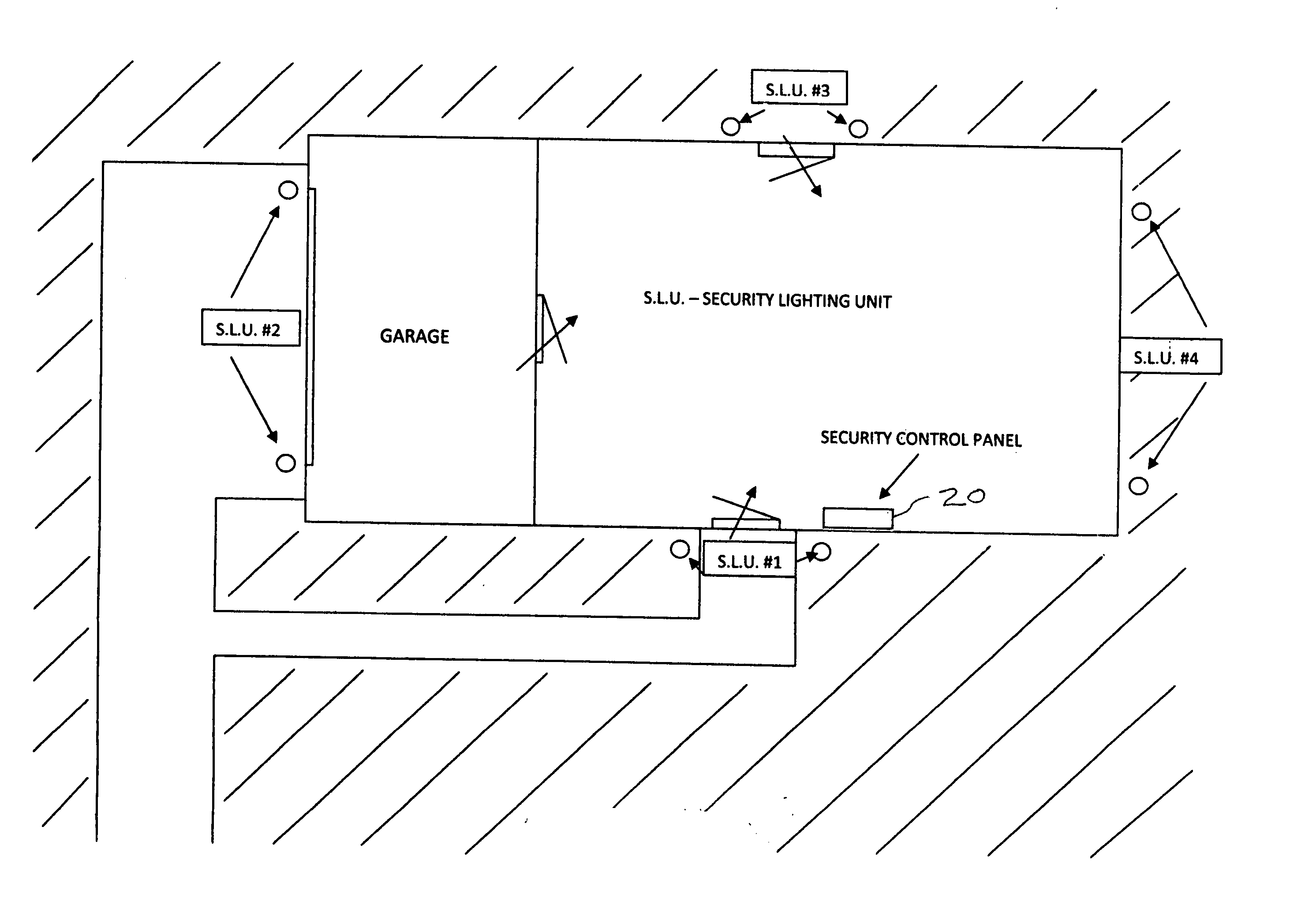
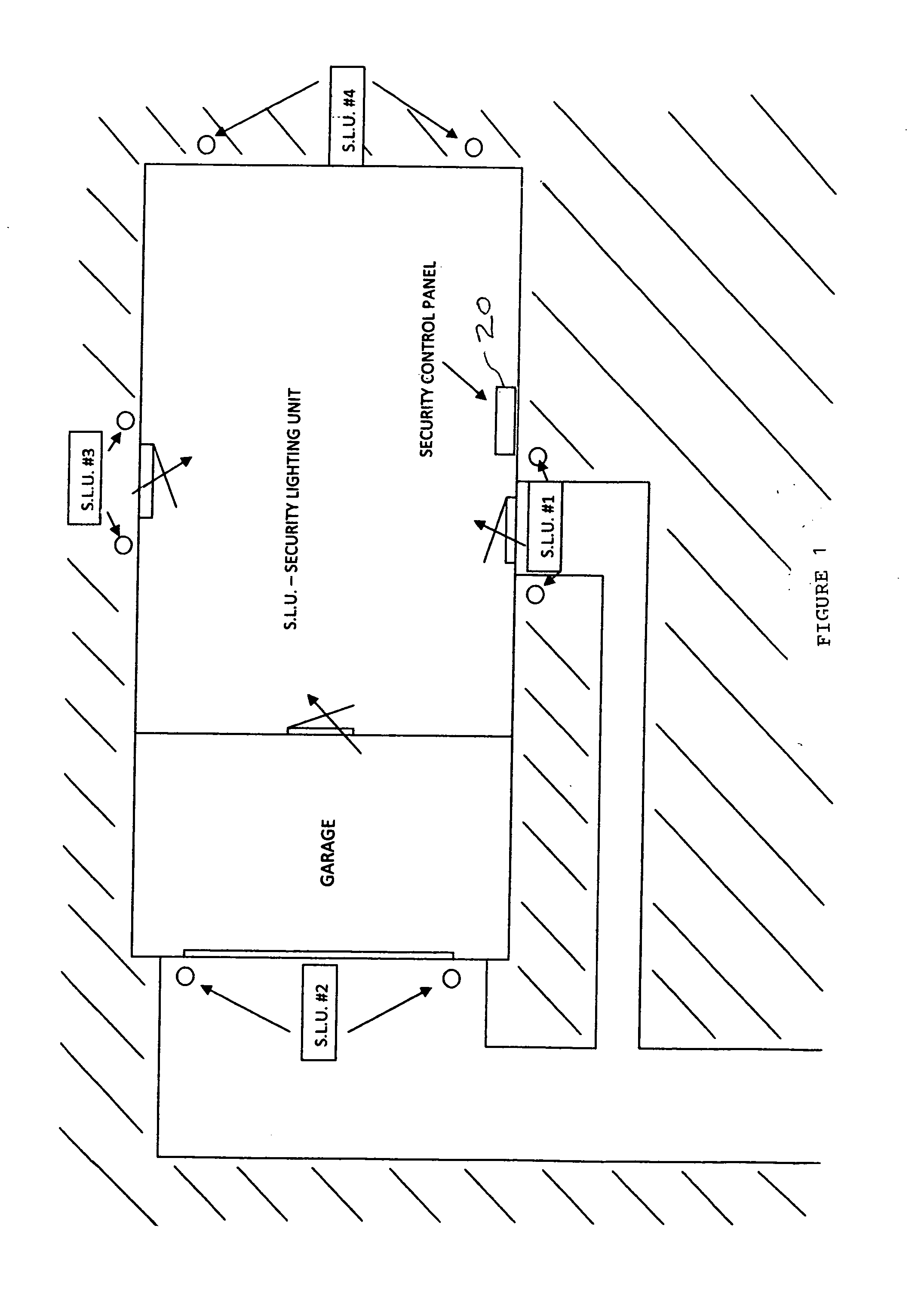
[0018]FIG. 1 is a top schematic view of a typical home having security lighting units (SLU's) placed at the following locations:[0019]at the front door of the home,[0020]at the main garage door of the home,[0021]at a rear location of the house,[0022]at a side or end location of the home.

[0023]The security lighting units may be placed at various other locations of the home as decided by the homeowner. Also, they may be placed at various locations on the grounds at the option of the system users.

[0024]A security control panel (SCP) is indicated schematically near the front door of the home. The SCP will be more fully described herein.

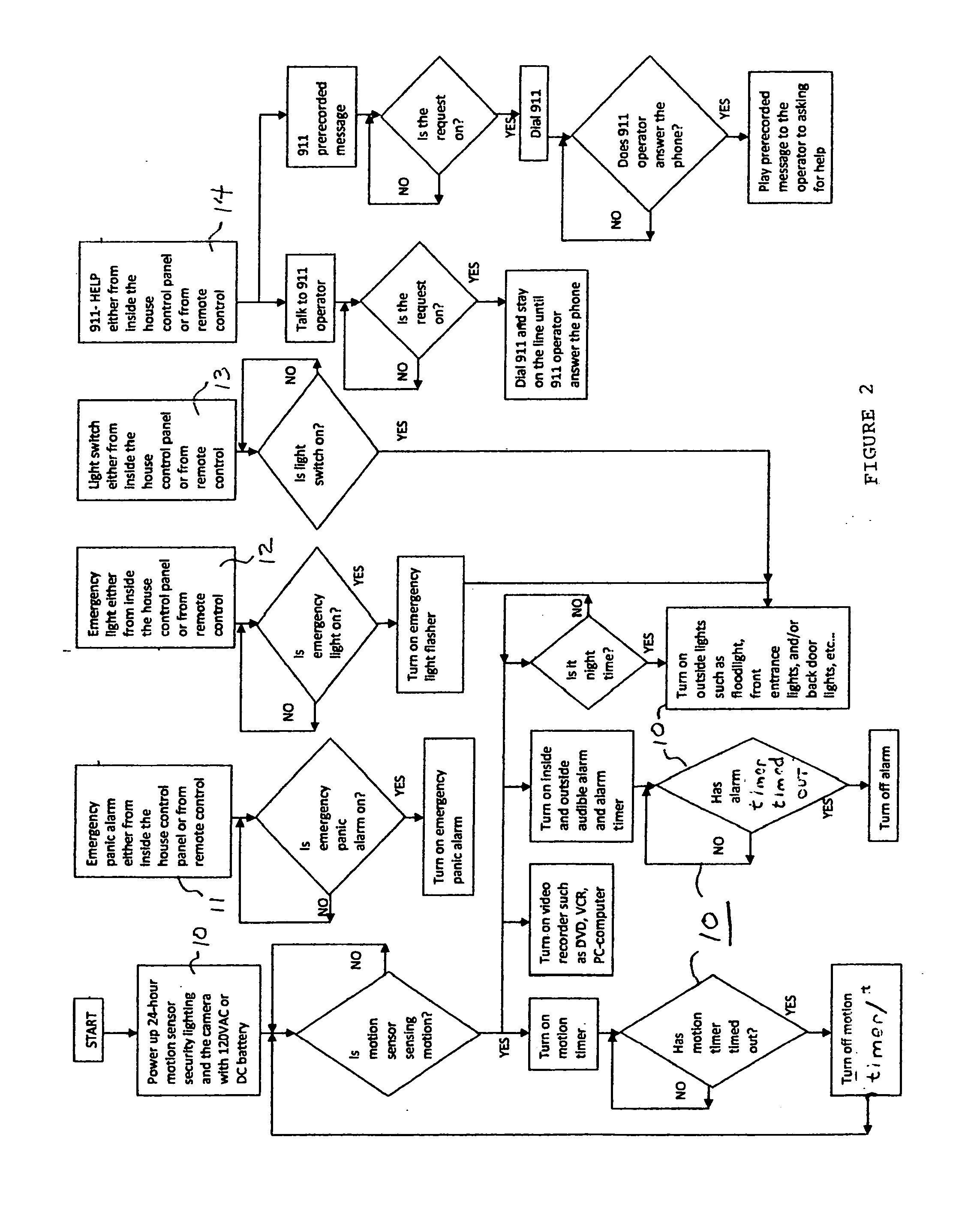
[0025]Referring to the drawing FIG. 2, the basic security lighting system operation is shown at the left and lower left of the figure. It includes motion sensors, security lights and cameras and various operational blocks as shown.

[0026]Referring further to the left hand portion of FIG. 2, it is seen that if a motion sensor is detecting motion, the follow...


PUM


Abstract

A security system and method which includes a main automatically acting circuit 10 and portions which may be manually activated by a user to provide better deterrence to a home invader or burglar (11-14). The manually activated portions turn on an audible alarm and/or lights which may or may not be in the automatic section. Thus, economy of manufacture with enhanced safety and security is achieved. A variable alarm system is thus presented to a potential intruder to more effectively terminate a possible home invasion or robbery. The method includes remote control devices and remote detection devices so a user can remotely stop a home invasion or burglary.

Description

BACKGROUND AND OBJECTS OF THE INVENTION[0001]The present invention is generally related to the home security arts and, in particular, to a novel system and method of use for the occupants and owners of a home which may be threatened.[0002]Prior art systems and methods have proven to be somewhat useful but have not proven to provide sufficient warning and options for action to the inhabitants of a home threatened with unlawful entry.[0003]Prior art systems have also not proven to be economical for widespread manufacture and not especially useful for panicked inhabitants of a home being threatened.[0004]Accordingly, it is an object of the present invention to set forth a novel home security system which sufficiently warns the occupants of a home being threatened.[0005]It is a further object to demonstrate a method which gives the home occupants multiple options for responding to a dangerous situation, such options being readily used by persons of any age or physical condition.[0006]It...

Claims


Application Information

Patent Timeline
IPC IPC(8): G08B15/00
CPCG08B15/00
Inventor NGUYEN, JAMES H.
Owner NGUYEN JAMES H
Why Eureka
Try Eureka