Fixation system for bones with a sensor and telemetry system

a technology of telemetry and fixation system, applied in the field of fixation system for bones with a sensor and telemetry system, can solve problems such as saving time and money

Inactive Publication Date: 2009-09-03
WOLTER DIETMAR
View PDF11 Cites 29 Cited by
  • Summary
  • Abstract
  • Description
  • Claims
  • Application Information

AI Technical Summary

Benefits of technology

[0015]Due to the fact that in the fixation system according to the invention the sensor and telemetry system is arranged on a separate plate, which can be connected with the connection support, the operator can decide at the end of the operation whether the fixation system must be equipped with the sensor and telemetry system. If it is not required, the sensor and telemetry system is omitted and only the fixation system is used. This saves time and money. It is easier for the operator to decide on the use of this combined system. However, if the patient needs the combined system, then the operator can simply connect the plate with the sensor and telemetry system to the fixation system.
[0017]In accordance with a preferred embodiment, the bone screw and through hole have devices for the angle-stable connection in a selectable angle alignment. In accordance with one embodiment, these devices are devices for the shaping of a thread between the bone screw and the through hole. This makes it possible to also connect in a permanently angle-stable manner a bone screw that can be inserted in variable angle alignments into the connection support with the connection support.
[0025]In accordance with another embodiment, the groove and the spring are conical. In accordance with one embodiment, the groove narrows to its base and / or the spring narrows to its free end. This makes it possible to press the spring into the groove under the gradual introduction of force and to hereby establish a particularly deep connection between the plate and the connection support.
[0026]In accordance with one embodiment, the plate is made out of a harder material than the connection support or vice versa so that a particularly deep connection is established between the plate and the connection support through the material deformation during the creation of the groove / spring connection. This ensures that the transfer of forces takes place in a permanent and even manner.
[0032]In accordance with one embodiment, the sensor and telemetry system has an antenna. The antenna enables a wireless transmission of the signals to the outside. In order to facilitate the wireless transmission of the signal to the outside, it can be advantageous to connect the sensor unit with an antenna, the end of which reaches under the skin. The partial absorption of the signal can thus be avoided through the soft shell.
[0033]In accordance with one embodiment, a memory and telemetry unit that can be placed under the skin is present with a receiver antenna that can be placed in the vicinity of the sensor and telemetry system. It is hereby possible to keep smaller the part of the sensor and telemetry system that is arranged on the fixation system. This simplifies the data transfer and facilitates the energy transport. In accordance with another embodiment, the sensor and telemetry system has an antenna for the wireless transmission of signals to the receiver antenna.

Problems solved by technology

This saves time and money.

Method used


Image

  • Fixation system for bones with a sensor and telemetry system
  • Fixation system for bones with a sensor and telemetry system
  • Fixation system for bones with a sensor and telemetry system

Examples


Embodiment Construction

[0046]While this invention may be embodied in many different forms, there are described in detail herein a specific preferred embodiment of the invention. This description is an exemplification of the principles of the invention and is not intended to limit the invention to the particular embodiment illustrated

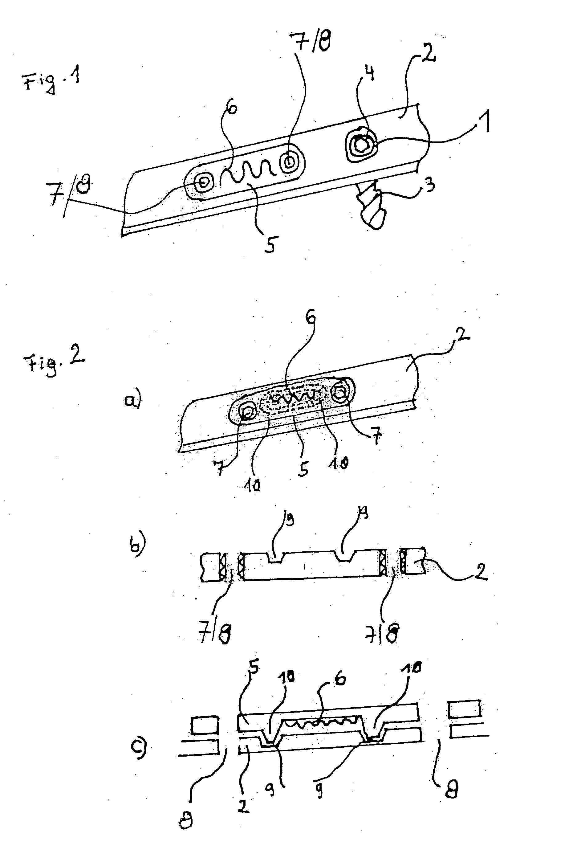
[0047]In the below explanation of various exemplary embodiments, corresponding components are labelled with the same reference numbers. In accordance with FIG. 1, a multi-directional, blockable bone screw 3 in the form of a bone plate is used in a through hole 1 of a connection support 2. The bone screw 3 can be screwed with a bone, wherein a thread is molded into the connection support 2 by a thread in the vicinity of the screw head 4.

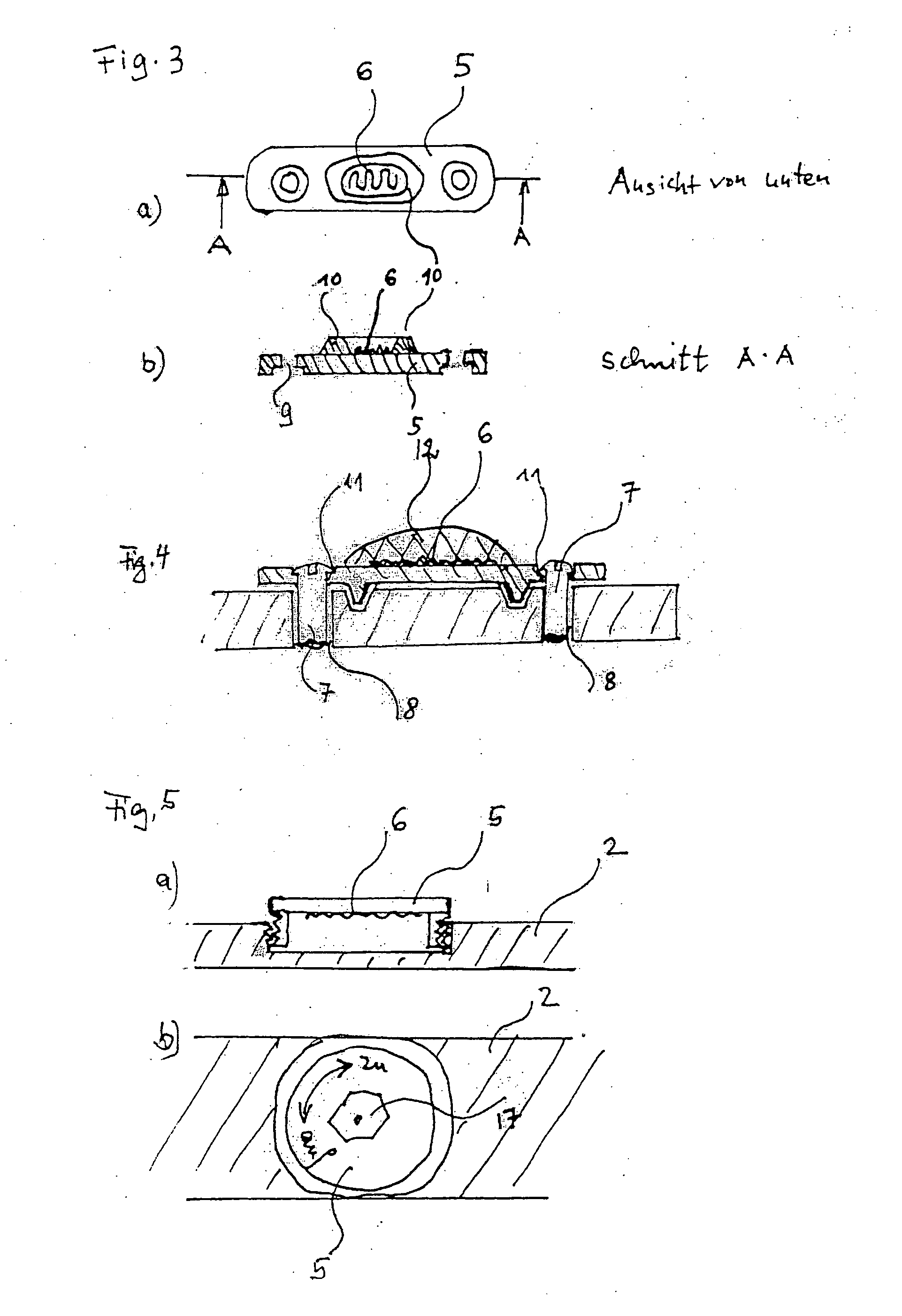
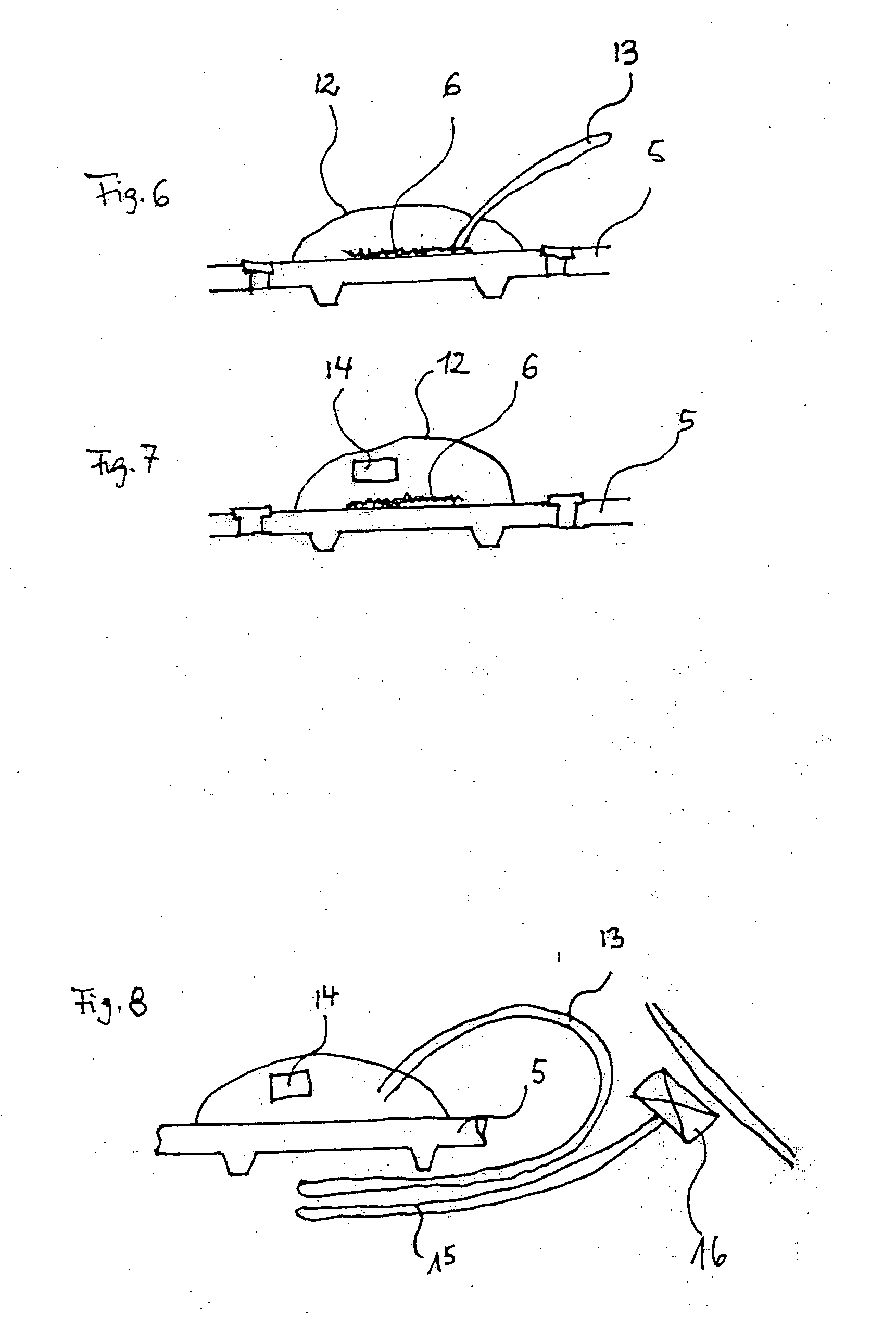
[0048]Furthermore, a separate plate 5 with a resistance strain gauge 6 is arranged on the connection support 2. The separate plate 5 is connected with the connection support 2 by means of other screws 7, which are screwed into the thread holes 8...


PUM


Abstract

Fixation system for bones with a connection support, at least one bone screw that can be inserted into a through hole of the connection support and a sensor and telemetry system, wherein the sensor and telemetry system is arranged on a separate plate, which can be connected with the connection support.

Description

CROSS-REFERENCE TO RELATED APPLICATIONS[0001]Not applicable.STATEMENT REGARDING FEDERALLY SPONSORED RESEARCH[0002]Not applicable.BACKGROUND OF THE INVENTION[0003]The invention relates to a fixation system for bones with a sensor and telemetry system.[0004]Fixation systems are used in osteosynthesis, wherein the connection support bridges the fracture and is connected with the bone fragments via at least one bone screw. The connection support is for example a bone plate, a marrow nail or external fixation. It is thereby advantageous if the bone screw in the connection support is blocked in a permanently angle-stable manner.[0005]Particularly advantageous is the selectability of the screw direction before the permanently angle-stable blocking of the bone screw in the connection support. The angle-stable connection of bone screw and connection support leads to a stability increase for the entire assembly trough the special type of transfer of forces and loads. This transfer is characte...

Claims


Application Information

Patent Timeline
Patent Type & Authority Applications(United States)
IPC IPC(8): A61B17/80A61B17/56A61B5/103
CPCA61B5/0031A61B5/4504A61B17/60A61B2562/0261A61B17/80A61B2017/00734A61B2019/464A61B17/72A61B2090/064
Inventor WOLTER, DIETMARCAPANNI, FELIX
Owner WOLTER DIETMAR
Why Eureka
Try Eureka