Attachment structure for ultrasonic sensor

a technology of ultrasonic sensors and attachment structures, which is applied in the direction of washstands, lighting support devices, instruments, etc., can solve the problems of increasing the size of the through-hole, reducing the effect of vibration transmission, and prolonging the reverberant or echo

Inactive Publication Date: 2009-09-10
DENSO CORP
View PDF5 Cites 28 Cited by
  • Summary
  • Abstract
  • Description
  • Claims
  • Application Information

AI Technical Summary

Benefits of technology

[0011]In view of the above points, it is an objective of the present invention to provide an attachment structure which provides coincidence between a center of an ultrasonic sensor an...

Problems solved by technology

Thus, when this fixation member is used for attaching an ultrasonic sensor having an ultrasonic transducer for both transmission and reception and a case receiving the ultrasonic transducer, there arises a problem that reverberant or echo remains lo...

Method used


Image

  • Attachment structure for ultrasonic sensor
  • Attachment structure for ultrasonic sensor
  • Attachment structure for ultrasonic sensor

Examples


first embodiment

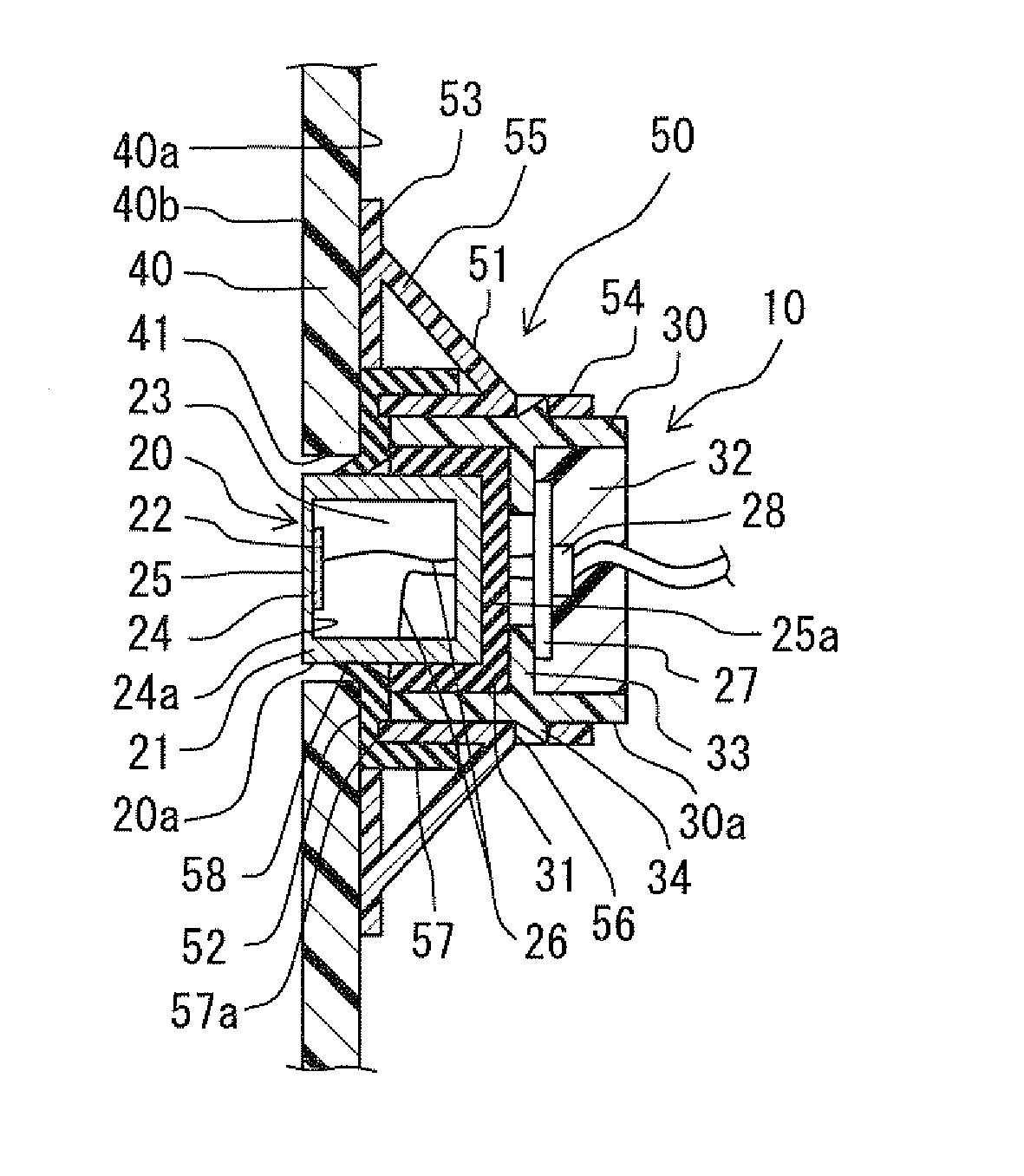
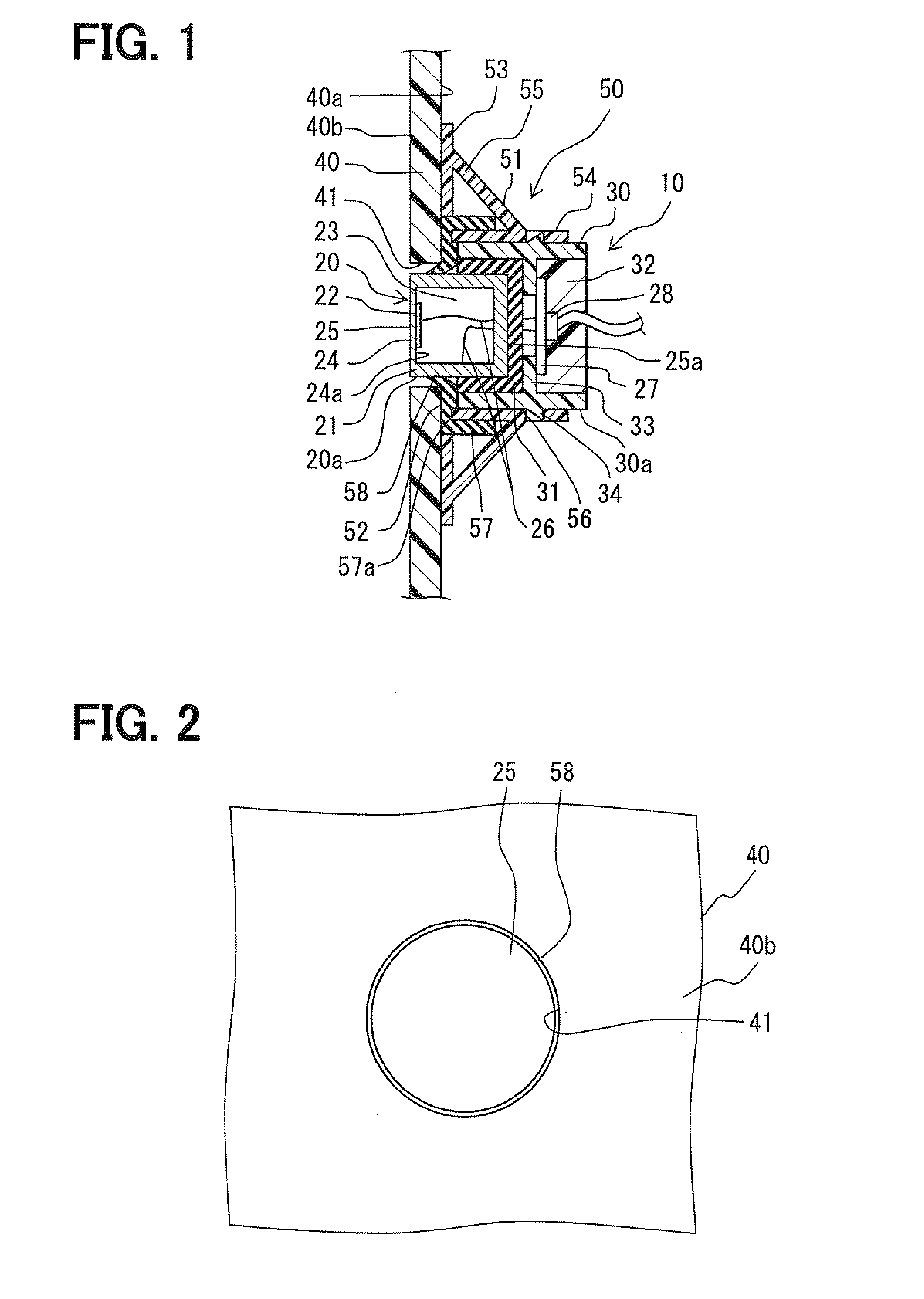
[0024]FIG. 1 is a cross sectional diagram illustrating an attachment structure for an ultrasonic sensor in accordance with a first embodiment. FIG. 2 is a plan view corresponding to FIG. 1, the view being taken from an outside of a vehicle. A direction in which a through-hole extends is refereed to hereinafter as a penetration direction, and a direction perpendicular to the penetration direction is referred to hereinafter as a perpendicular direction.

[0025]The ultrasonic sensor is attached to a front part of a vehicle, a rear part of the vehicle, or four-cornered parts of a bumper so that the ultrasonic sensor can detect an obstacle existing around the vehicle. As shown in FIG. 1, the ultrasonic sensor 10 includes: an ultrasonic transducer 20 (e.g., so called a microphone) for both of transmission and reception; a case 30 receiving the ultrasonic transducer 20 so that an oscillation surface 25 of the ultrasonic transducer 20 is exposed; and a vibration insulation member 31 disposed ...


PUM


Abstract

Disclosed is an ultrasonic sensor attachment structure which provides coincidence between a center of the ultrasonic-sensor and that of a through-hole in a simple way, and which restricts unwanted-vibration-transmission between a wall-member of a movable-body and an ultrasonic-transducer without spoiling design. According to the structure, the sensor, which includes the ultrasonic-transducer, a case receiving the ultrasonic-transducer and a vibration-insulation-member for vibration-transmission-suppression, is attached to the wall-member having the through-hole, so that an oscillation-surface is exposed to an outer-surface side through the through-hole. The ultrasonic-sensor is fixed by a fixation-member so that the oscillation-surface and an outer-surface of the wall-member are on a substantially same plane. The fixation-member includes a positioning-member, which provides substantial coincidence between a center of the oscillation-surface of the ultrasonic-sensor and that of the through-hole, and which is made of a material suppressible of vibration-transmission between the ultrasonic-transducer and the wall-member.

Description

CROSS REFERENCE TO RELATED APPLICATION[0001]The present application is based on Japanese Patent Application No. 2008-58422 filed on Mar. 7, 2008, the disclosure of which is incorporated herein by reference.BACKGROUND OF THE INVENTION[0002]1. Field of the Invention[0003]The present invention relates to an attachment structure for attaching an ultrasonic sensor to a wall member of a movable body such as a vehicle bumper having a through-hole.[0004]2. Description of Related Art[0005]There has been proposed such an attachment structure for an ultrasonic sensor that a module (e.g., ultrasonic sensor) is fixed to a retain part (e.g., fixation member) attached to an inside (e.g., inner surface) of a bumper having a through-hole so that an end surface (e.g., an oscillation surface) of a head part of the ultrasonic sensor and an outer surface of the bumper are on the same plane. For instance, Patent Document 1 shows such attachment structures.[0006]In a case of the above structure, the oscil...

Claims


Application Information

Patent Timeline
IPC IPC(8): G01N29/00A47B96/06
CPCG10K9/22
Inventor SATO, YOSHIHISAKAWASHIMA, YASUHIRO
Owner DENSO CORP
Why Eureka
Try Eureka