Reflex, magnifying optical system

a technology of optical system and lens, applied in the field of reflex, can solve the problems of insufficient means for reducing error sensitivity, significant deterioration of optical performance, and high error sensitivity of lenses arranged on the incident side or on the emission side of prisms that refract the optical path

Inactive Publication Date: 2009-09-10
TAMRON
View PDF7 Cites 36 Cited by
  • Summary
  • Abstract
  • Description
  • Claims
  • Application Information

AI Technical Summary

Benefits of technology

[0036]An object of the present invention is to provide a compact, reflex, magnifying optical system in which the deterioration and variation of optical performance is prevented by reducing error sensitivity. Particularly, with respect to the first lens L1 and the second lend L2, which are apt to cause error sensitivity, the following conditions are set in the present invention to reduce such error sensitivity.

Problems solved by technology

The lens arranged on the incident side or on the emission side of the prism that refracts the optical path tends to have high error sensitivity (e.g., tilt error).
High error sensitivity is undesirable and leads to significant deterioration of optical performance.
Each of the reflex optical systems disclosed in the publications place great emphasis on achieving reductions in the size of the optical system and in doing so, a problem arises in that the means for reducing the error sensitivity is insufficient.

Method used


Image

  • Reflex, magnifying optical system
  • Reflex, magnifying optical system
  • Reflex, magnifying optical system

Examples


first embodiment

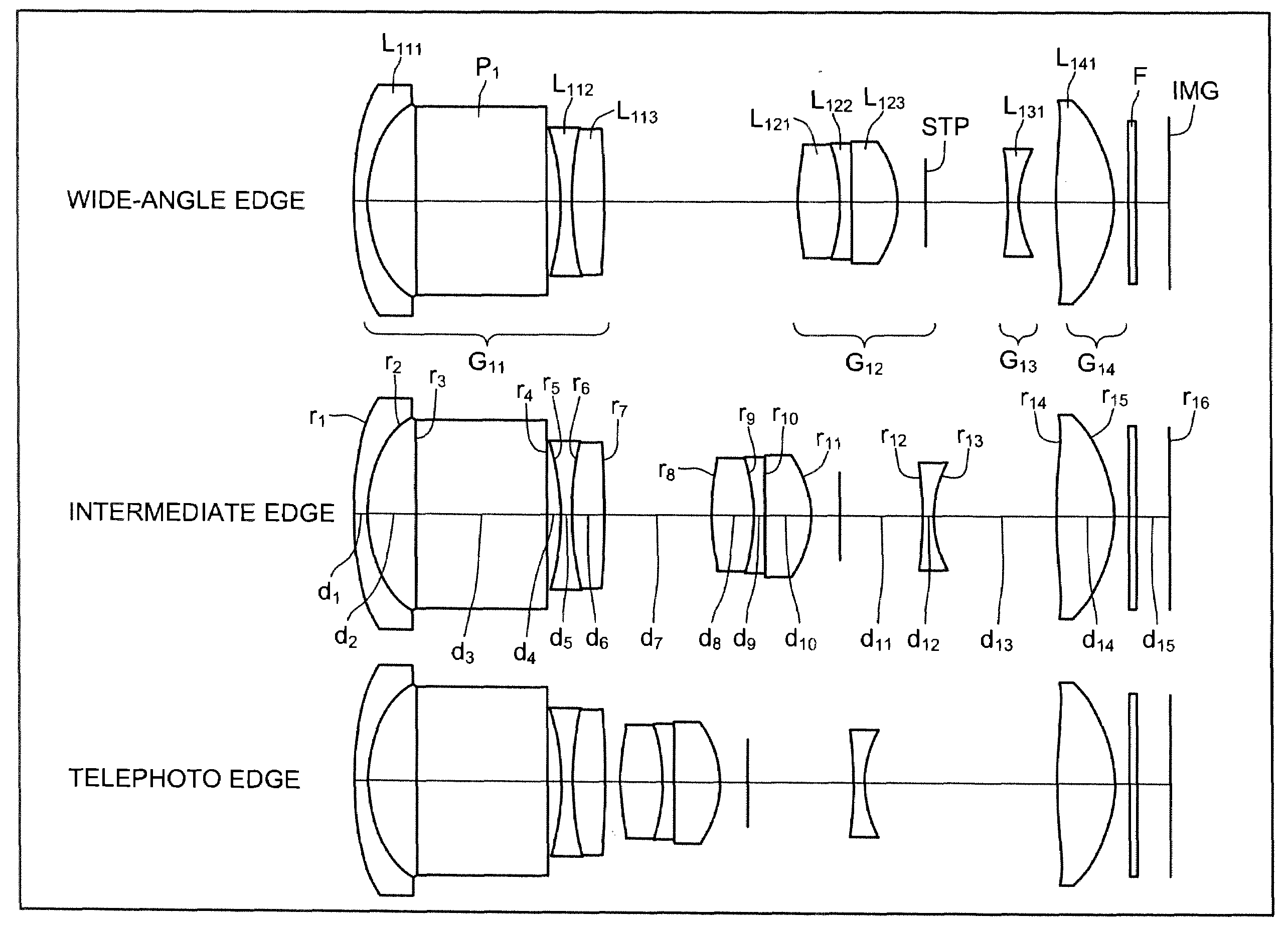
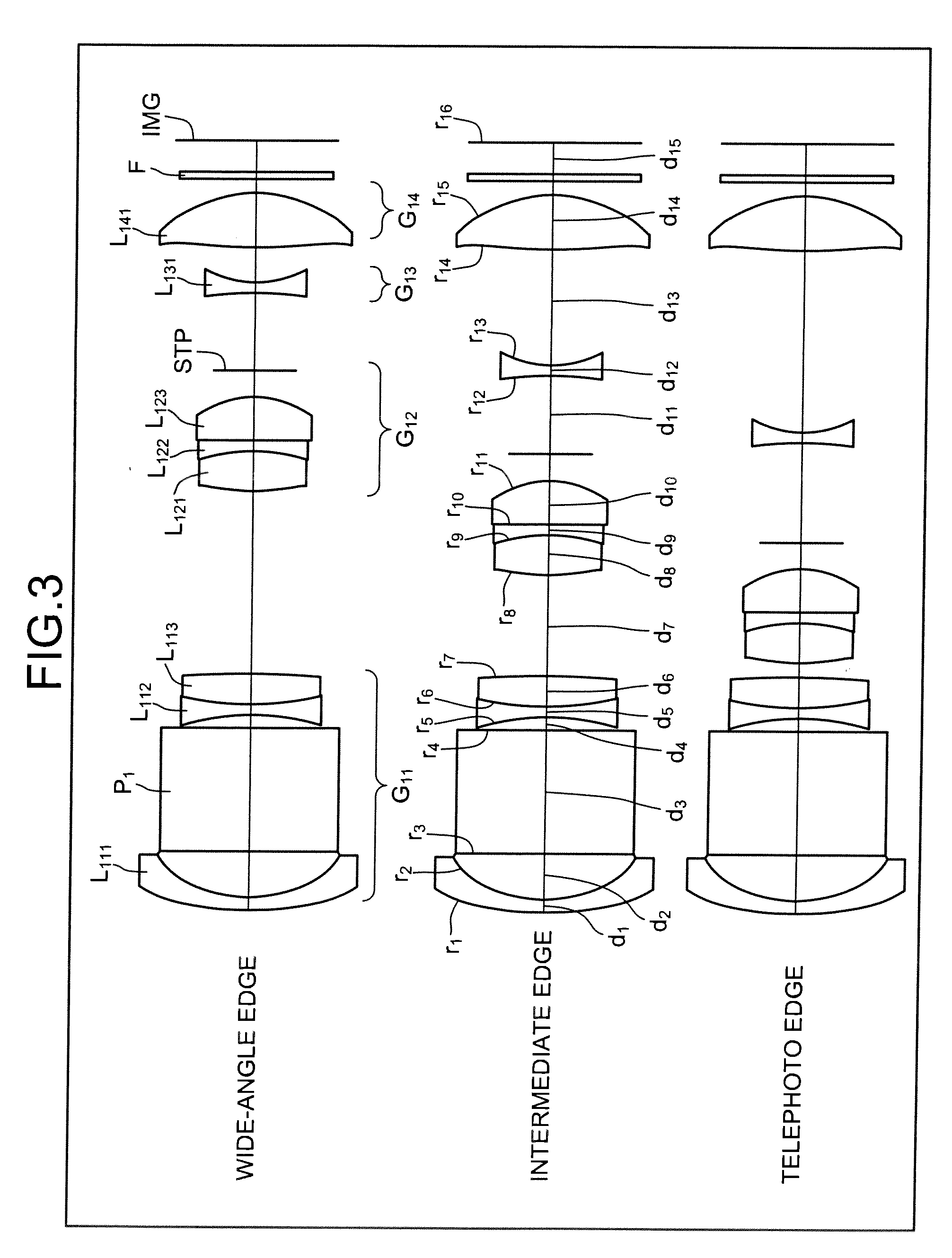
[0049]FIG. 3 is a cross sectional view, along the optical axis, of a reflex, magnifying optical system according to a The reflex, magnifying optical system includes sequentially from the object side (object not depicted), a first lens group G11 having a negative refractive power, a second lens group G12 having a positive refractive power, a third lens group G13 having a negative refractive power, and a fourth lens group G14 having a positive refractive power. The reflex, magnifying optical system varies magnification by moving the second lens group G12 and the third lens group G13 along the optical axis. The first lens group G11 and the fourth lens group G14 are fixed at all times. A filter F including an IR (infrared) cut filter, a low-pass filter, a cover glass, etc. is arranged between the fourth lens group G14 and an image plane IMG. The filter F is provided as necessary and may be omitted if not necessary. A light receiving surface of an imaging device such as a charge-coupled...

second embodiment

[0152]FIG. 13 is a cross sectional view, along the optical axis, of a reflex, magnifying optical system according to a The reflex, magnifying optical system includes sequentially from the object side (object not depicted) a first lens group G21 having a negative refractive power, a second lens group G22 having a positive refractive power, a third lens group G23 having a negative refractive power, and a fourth lens group G24 having a positive refractive power. The reflex, magnifying optical system varies magnification by moving the second lens group G22 and the third lens group G23 along the optical axis. The first lens group G21 and the fourth lens group G24 are fixed at all times. A filter F including an IR cut filter, a low-pass filter, a cover glass, etc. is arranged between the fourth lens group G24 and an image plane IMG. The filter F is provided as necessary and may be omitted if not necessary. A light receiving surface of an imaging device such as a CCD and a CMOS is provide...


PUM


Abstract

A first lens group in a reflex, magnifying optical system includes sequentially from the side of an object, a first lens that has a negative refractive power and is a meniscus lens having a concave aspect facing toward an image, an optical element (prism) that refracts an optical path, a second lens having a negative refractive power and a concave aspect facing toward the object, and a third lens having a positive refractive power. A portion of an image-side aspect of the first lens abuts a plane of incidence of the optical element. A portion of an object-side aspect of the second lens abuts a plane of transmission of the optical element.

Description

BACKGROUND OF THE INVENTION[0001]1. Field of the Invention[0002]The present invention relates to a reflex, magnifying optical system.[0003]2. Description of the Related Art[0004]Recently, accompanying demand for smaller sized imaging devices, there is demand for smaller sized lenses mounted on the imaging devices as well. In response, reflex optical systems employing a prism in an optical path to refract the optical path have been proposed, such as those disclosed in Japanese Patent Application Laid-Open Publication Nos. 2005-128065, 2004-334070, 2004-333721, 2007-232974, and 2004-163477.[0005]Reflex optical systems disclosed in the publications achieve a reduced depth (thickness) by refracting the light path. Consequently, mounting of these reflex optical systems has enabled imaging devices to have shortened depths as well.[0006]The lens arranged on the incident side or on the emission side of the prism that refracts the optical path tends to have high error sensitivity (e.g., tilt...

Claims


Application Information

Patent Timeline
Patent Type & Authority Applications(United States)
IPC IPC(8): G02B15/14
CPCG02B17/0896G02B15/177G02B15/144511
Inventor KUBOTA, TAKASHI
Owner TAMRON
Why Eureka
Try Eureka