Compact log splitter

a log splitter and compact technology, applied in the field of log splitters, can solve the problems of inconvenient use of horizontal splitters, inefficiency in the splitting process, and the required strength of log splitter components, and achieve the effect of minimizing the size of the splitter

Active Publication Date: 2009-09-17
NORTHERN TOOL & EQUIP
View PDF17 Cites 23 Cited by
  • Summary
  • Abstract
  • Description
  • Claims
  • Application Information

AI Technical Summary

Benefits of technology

The invention describes a cutting tool used in construction materials processing which has a unique design feature called a splitting device. This device helps reduce the size of the machine by eliminating the necessity of creating a long support structure to accommodate the movement of its parts.

Problems solved by technology

The technical problem addressed in this patent is the need for a small and compact log splitter that can be easily shipped, transported, and stored when not in use. Current horizontal-type log splitters are large and bulky, requiring significant strength to counteract the hydraulic force they generate. Additionally, they must have a support structure that matches the length of the hydraulic cylinder driving the splitting wedge, resulting in a continuous support structure that further adds to their size. There is a need for a more efficient and compact log splitter design that allows for easy handling and storage.

Method used


Image

  • Compact log splitter
  • Compact log splitter
  • Compact log splitter

Examples


Embodiment Construction

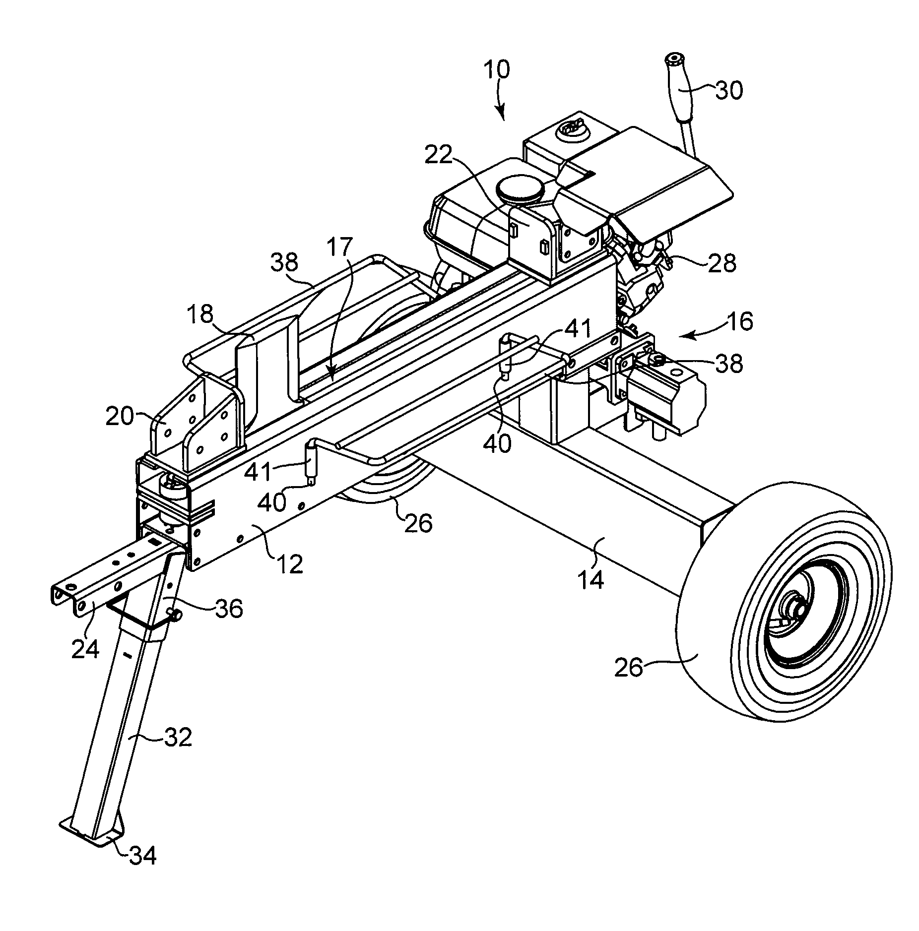
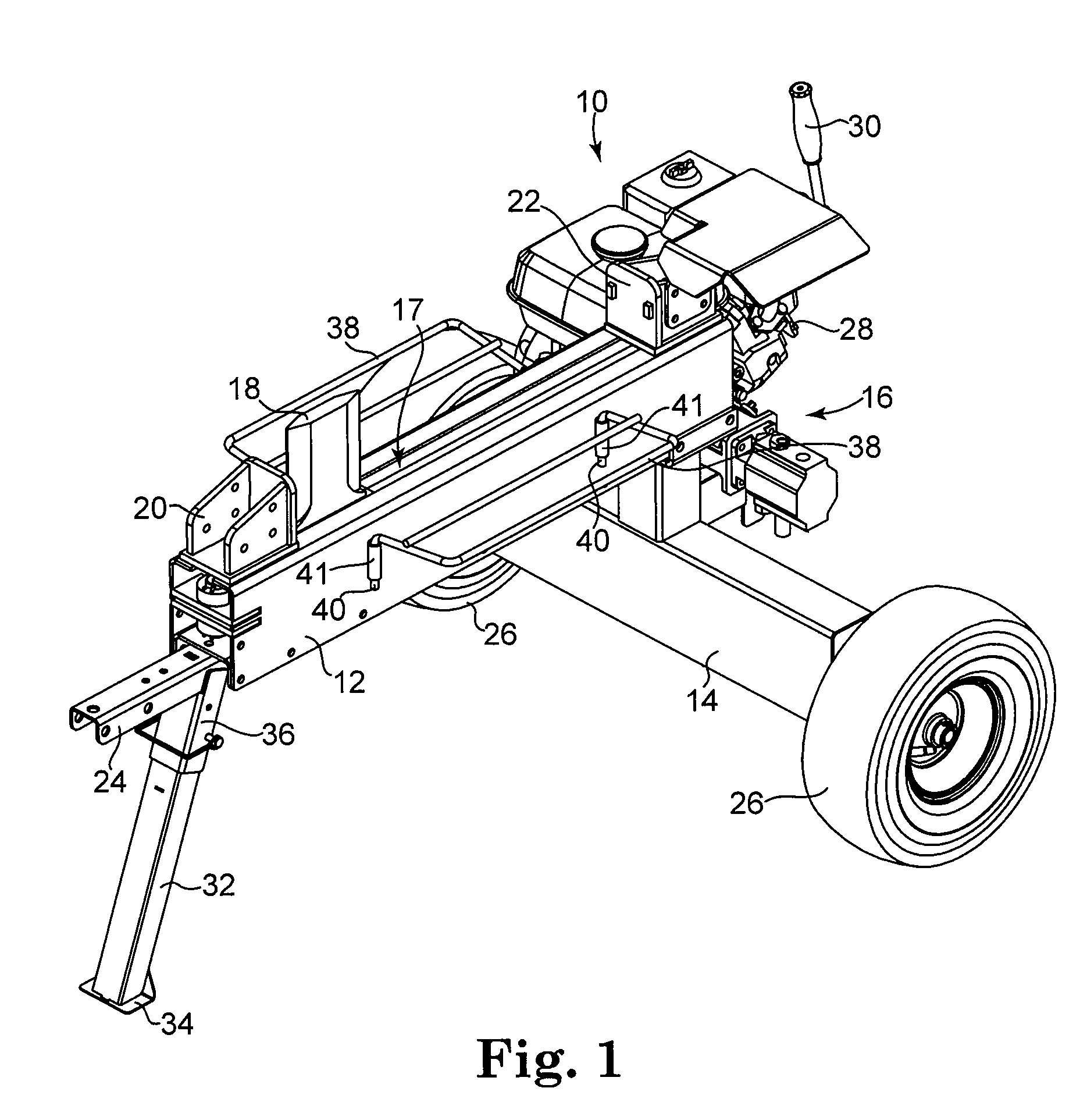
[0017]FIG. 1 is a perspective view of a log splitter 10 in accordance with the present invention. As shown in FIG. 1, log splitter 10 includes support structure 12, wheel base 14, drive system 16 connected to support framework 12 and wheel base 14, a splitting device 17 having a splitting wedge 18 operably coupled to drive system 16, first stop member 20, and second stop member 22. Log splitter 10 shown in FIG. 1 is a trailer-type log splitter having hitch 24 and wheels 26 in order to couple log splitter 10 to a transport vehicle, allowing the splitter to be moved from location to location. Alternatively, those skilled in the art will appreciate that log splitter 10 may be stationary, variable in size and / or designed to be disassembled into smaller components for transportation, storage, etc., and reassembled when necessary for use.

[0018]Drive system 16 includes pump and motor assembly 28, control handle 30, a control valve (not shown), and a hydraulic cylinder or drive mechanism (n...


PUM


Abstract

A log splitter comprises a support structure having a first end, a second end, and an open center portion defined therebetweeen, a splitting device slidably coupled to the support structure, and a drive mechanism for driving movement of the splitting device through a splitting zone. The splitting device comprises an elongate beam having an outer surface, a first end, a second end, and an open center portion between the first end and the second end, and a splitting wedge coupled to the outer surface of the elongate beam and having at least one splitting surface formed thereon. The elongate beam is disposed within the open center portion of the support structure. The drive mechanism is disposed within the open center portion of the elongate beam, and is coupled on a first end to the first end of the support structure and on a second end to the second end of the elongate beam.

Description


Claims


Application Information

Patent Timeline
Owner NORTHERN TOOL & EQUIP
Why Eureka
Try Eureka