Concave-convex surface inspection apparatus

a technology of concave and convex surfaces, applied in the direction of distance measurement, material analysis, instruments, etc., can solve the problems of blind spots generated, the shape of the hidden portion of the groove is not measured,

Inactive Publication Date: 2009-09-17
AISIN SEIKI KK
View PDF5 Cites 17 Cited by
  • Summary
  • Abstract
  • Description
  • Claims
  • Application Information

AI Technical Summary

Benefits of technology

[0006]According to an aspect of the present invention, a concave-convex surface inspection apparatus includes a slit light source unit emitting a slit light to a concave-convex surface of an object to be inspected, an image-taking unit taking an image of the concave-convex surface illuminated by the emitted slit light with an imaging optical axis intersecting with an optical axis of the slit light with a narrow-angle equal to or narrower than 30 degrees, and an evaluation section obtaining a three dimensional shape of the concave-convex surface based on the image taken by the image-taking unit and evaluating the obtained three dimensional shape, wherein the slit light source unit includes a slit light source and a cylindrical lens converting the slit light projected by the slit light source into parallel light beams parallel to the optical axis of the projected slit light, the image-taking unit includes a telecentric lens unit and an image-taking section having an imaging surface tilted relative to the imaging optical axis at a tilt angle being defined in accordance with an intersection angle of the optical axis of the slit light and the imaging optical axis for increasing a focusing range of the concave-convex surface, and the image-taking unit further includes a P polarizer positioned on the imaging optical axis for suppressing an incidence of an S polarized light to the imaging surface.

Problems solved by technology

As a result, a problem arises that a shape of the hidden portion of the groove is not measured.
However, an optical axis of the slit light and an imaging optical axis are inclined relative to the vertical axis at 45 degrees, and thus blind spots are generated when taking an image of a surface having a number of relatively deep grooves.

Method used


Image

  • Concave-convex surface inspection apparatus
  • Concave-convex surface inspection apparatus
  • Concave-convex surface inspection apparatus

Examples


Embodiment Construction

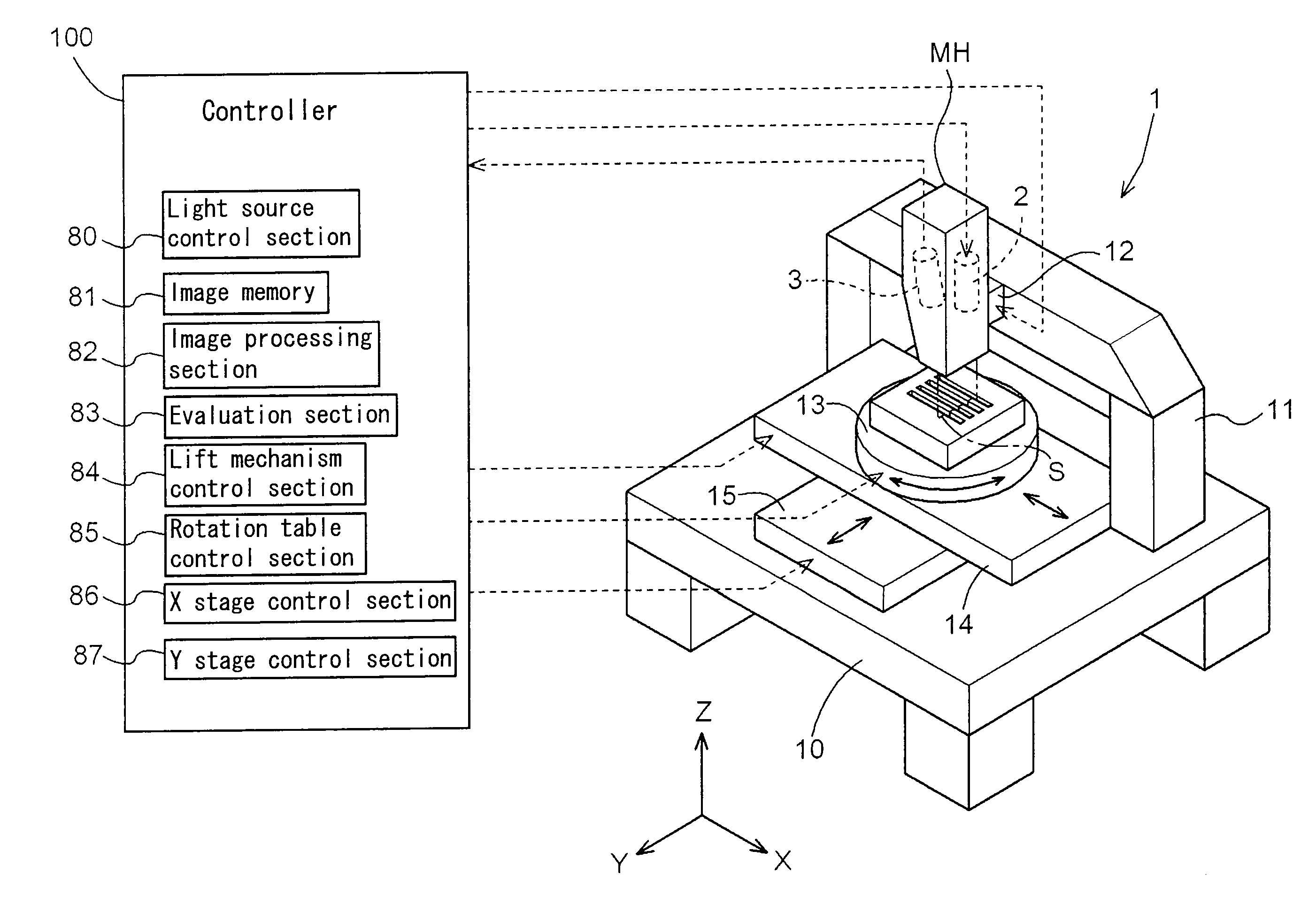
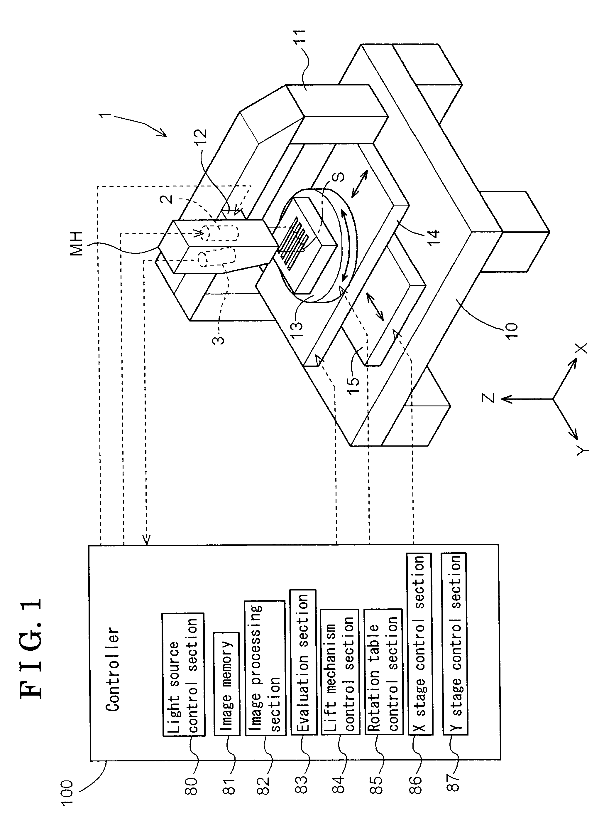
[0014]As a concave-convex surface inspection apparatus of one embodiment of the invention, a surface inspection apparatus inspecting cross-sections of a number of deep linear grooves formed on a surface of an object to be inspected in a manner that the grooves are aligned with one another will be described hereinbelow with reference to the attached drawings. FIG. 1 is a perspective view schematically illustrating a structure of the surface inspection apparatus.

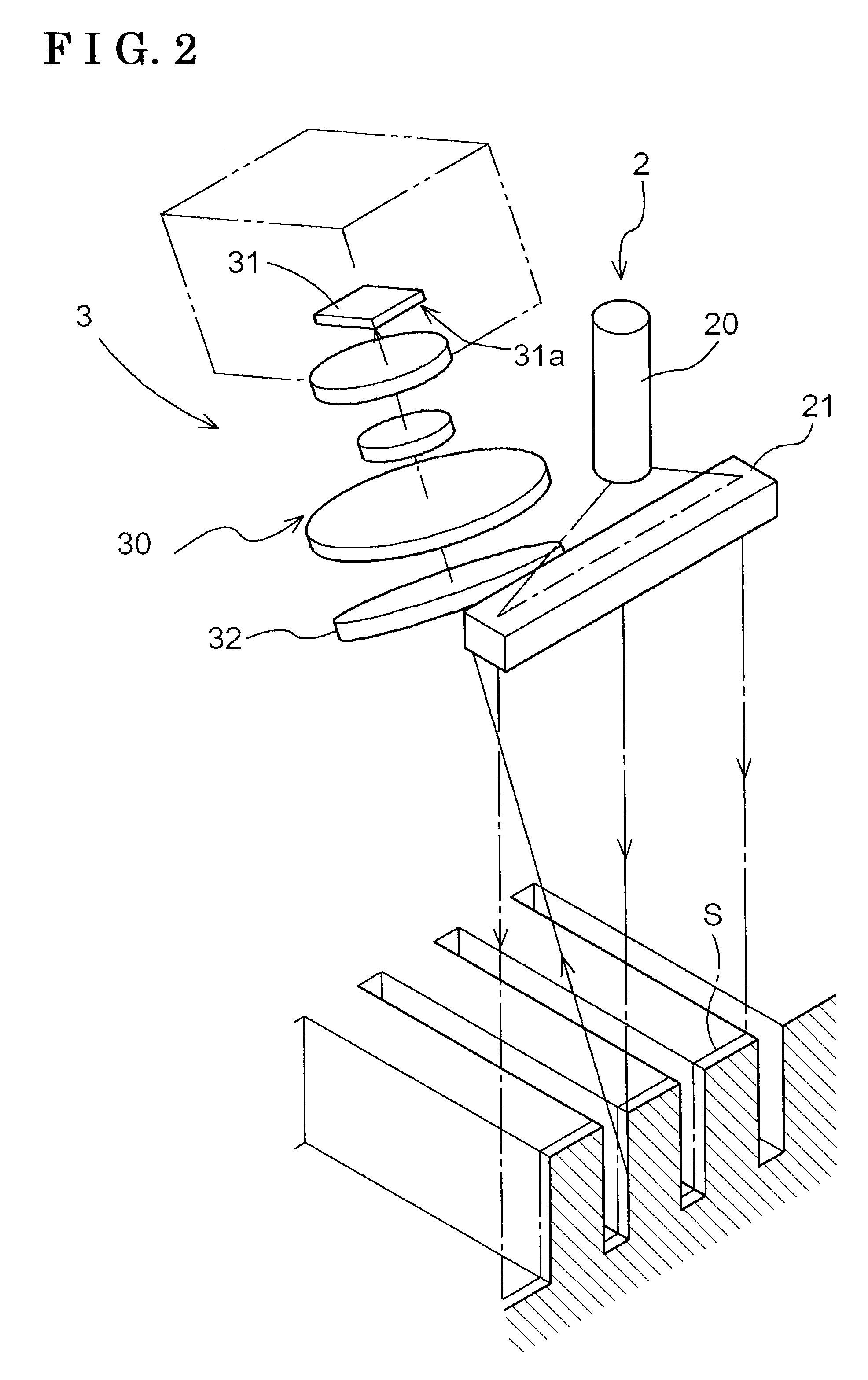
[0015]The surface inspection apparatus includes a measurement device 1 and a controller 100. The controller 100 controls the measurement device 1 and evaluates measurement results obtained tom the measurement device 1. The measurement device 1 includes a slit light source unit 2 which is a laser type and emits, i.e., projects, a slit light, and an image-taking unit 3 taking an image of an area of the object to be inspected which is emitted, i.e., illuminated, by the slit light. The slit light source unit 2 and the image-taking...


PUM


Abstract

A concave-convex surface inspection apparatus includes a slit light source unit emitting a slit light to a concave-convex surface of an object to be inspected, an image-taking unit taking an image of the concave-convex surface illuminated by the emitted slit light with an imaging optical axis intersecting with an optical axis of the slit light with a narrow-angle equal to or narrower than 30 degrees, and an evaluation section obtaining a three dimensional shape of the concave-convex surface and evaluating the obtained three dimensional shape, wherein the slit light source unit includes a slit light source and a cylindrical lens, the image-taking unit includes a telecentric lens unit, an image-taking section having an imaging surface tilted relative to the imaging optical axis for increasing a focusing range of the concave-convex surface, and a P polarizer.

Description

CROSS REFERENCE TO RELATED APPLICATIONS[0001]This application is based on and claims priority under 35 U.S.C. §119 to Japanese Patent Application 2008-064458, filed on Mar. 13, 2008, the entire contents of which is incorporated herein by reference.FIELD OF THE INVENTION[0002]The present invention relates to a concave-convex surface inspection apparatus.BACKGROUND[0003]As a concave-convex surface inspection apparatus, an apparatus having a slit light source emitting a slit light to an object to be measured, a camera taking a slit image of the object to be measured when the object to be measured is illuminated with the slit light, and an image processing section obtaining three dimensional data from the slit image taken by the camera is known (for example, JP H4-301707A, paragraphs 0005 and 0006 and FIG. 3). In the known device, the slit light beams are diffused in a shape of a fan relative to an optical axis of the slit light. Therefore, when inspecting a surface on which a number of...

Claims


Application Information

Patent Timeline
Patent Type & Authority Applications(United States)
IPC IPC(8): G01C3/00
CPCG01B11/25
Inventor TODA, MASATAKAYOSHIKAWA, TOSHIHIKOINUZUKA, KATSUYAKUNO, KOJI
Owner AISIN SEIKI KK
Why Eureka
Try Eureka