
Lightwall instrument

Inactive Publication Date: 2009-09-17
WANG EUGENE
View PDF18 Cites 0 Cited by
  • Summary
  • Abstract
  • Description
  • Claims
  • Application Information

AI Technical Summary

Benefits of technology

[0017]An object of the present invention is to provide a method and instrument to provide a lightwall in order to improve photograph effect.
[0018]Another object of the present invention is to provide a lightwall instrument which can produce a virtually single wall of light source having a relatively large coverage to reduce hot spots from multiple soft boxes to be used for such large coverage conventionally.
[0023]Another object of the present invention is to provide a lightwall instrument to reduce lighting reflection.
[0024]Another object of the present invention is to provide a lightwall instrument to reduce noise (hot spots).
[0027]Another object of the present invention is to provide an innovative diffuser layer which can evenly diffuse light and provide softness light source.

Problems solved by technology

First, the coverage of the light source needs to be large.
Also, because most objects have irregular surface, the extruded parts will leave a shadow behind.
For example, people's faces are quite easy to have shadows and destroy the effect.
Second, the quality of the light is required.
There are several disadvantages limiting the usage of soft box.
First, the color temperature of soft box light is not even.
Second, the depth of the light bulb can't be adjusted.
Third, the dimension of the soft box is generally limited.
Most of currently using soft box is only in foot square, it is difficult to cover object like an adult human.
For other objects such as automobile, special made soft boxes are needed but are very expensive.
Generally the disputer has only a flat surface, and can not provide curved surface.
This will enlarge the reflection image of the light source (hot spot) and damage the effect of the photograph.
Also, it is not convenient to use the soft box in studio.
But the soft box is heavy, and the dimension is relatively larger than the base of the tripod, therefore it is not easy to move the soft box, and make it stand stably.
Besides the limitation of the equipment, there is also some misunderstanding of using the light source.
This may diminish some shadows, but it doesn't help the image of the front face, and causes more hot spots.

Method used


Image

  • Lightwall instrument
  • Lightwall instrument
  • Lightwall instrument

Examples


Embodiment Construction

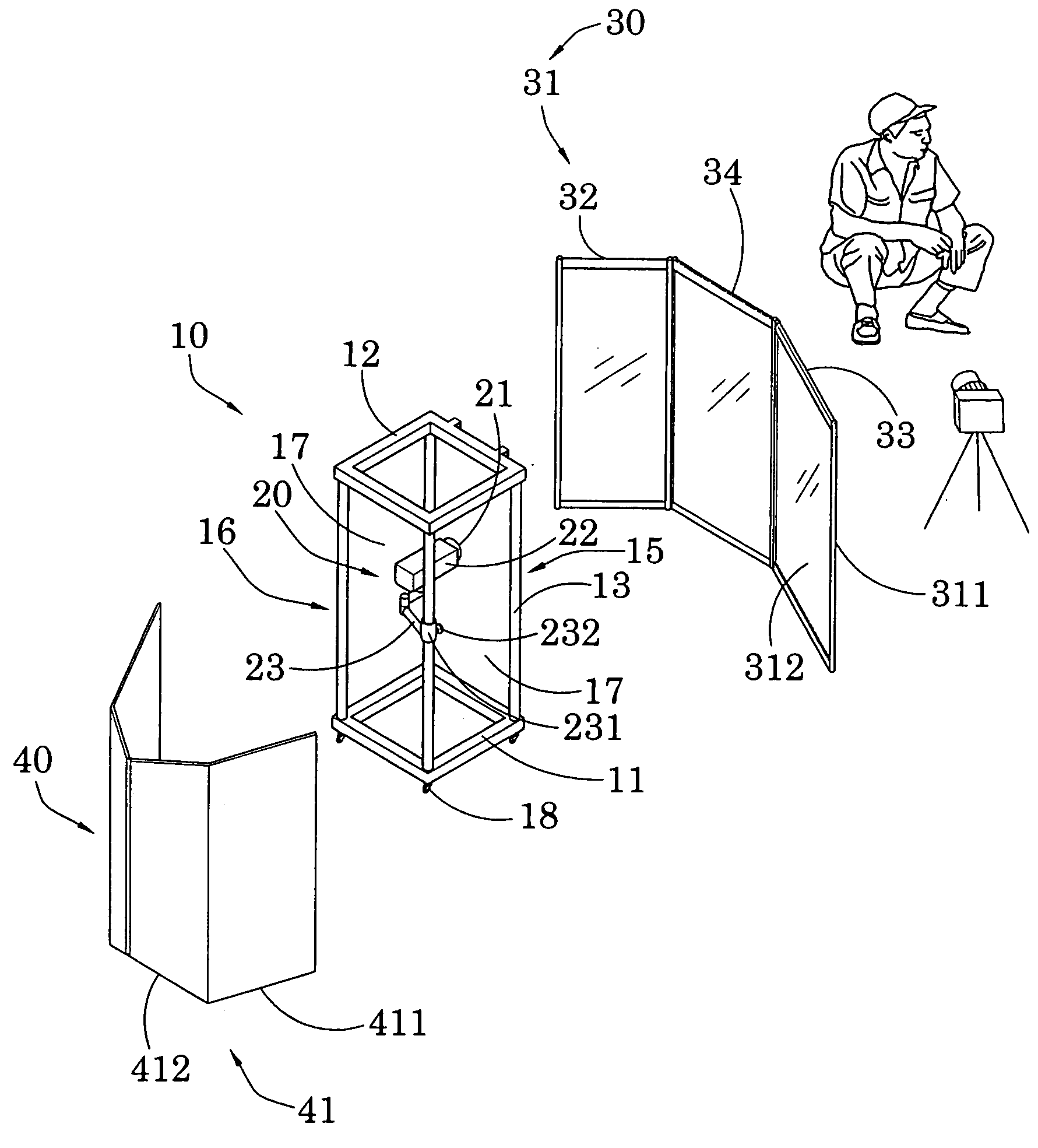
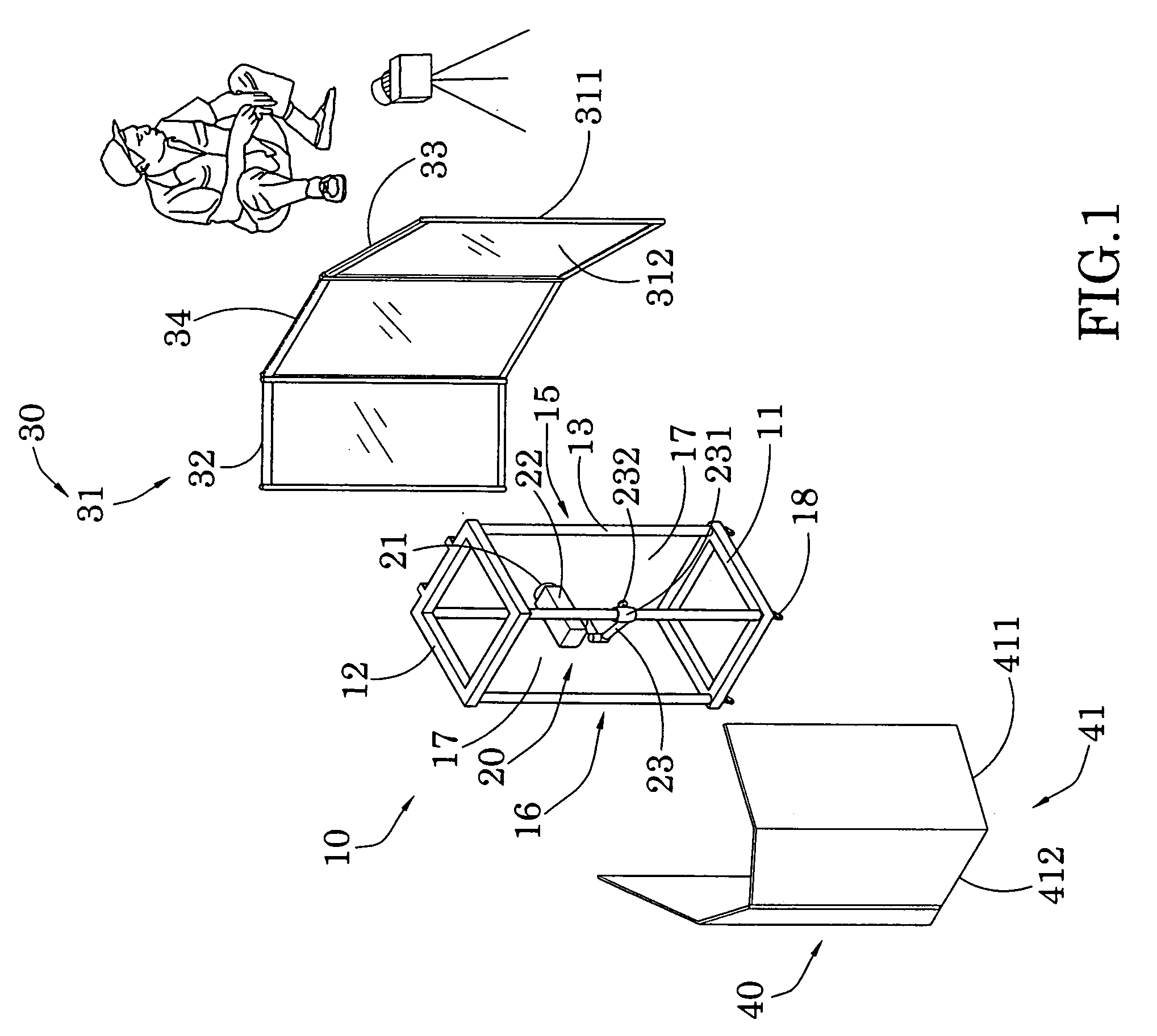
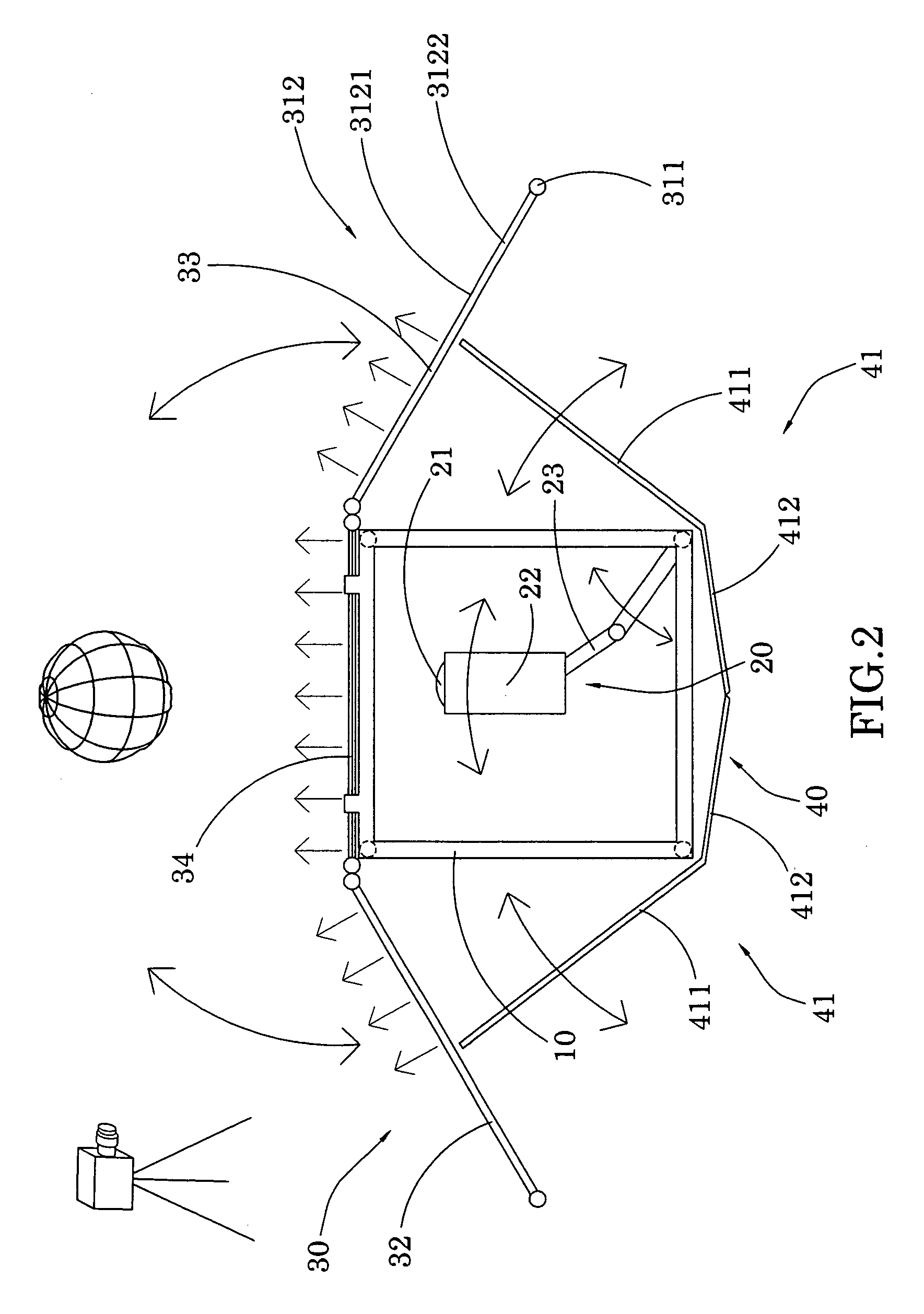
[0048]Referring to FIG. 1 of the drawings of the present invention, a lightwall instrument embodied as photographic light source for better effect of photographs and film is illustrated, in which the lightwall instrument comprises a supporting frame 10, a light source 20, a diffuser wall 30, and a shading arrangement 40. The supporting frame 10 comprises a square-shaped bottom frame 11, a square-shaped top frame 12, and four columns 13 extended between corners of the bottom frame 11 and corners of the top frame 12.

[0049]In a preferred embodiment of the present invention, the bottom frame 11 and the top frame 12 is embodied to have the same size of 600 mm×500 mm. The four columns 13 connect the four corners of the bottom frame 11 and the top frame 12 respectively to form a cubic frame. This cubic frame has a front face 15, a back face 16, and two side faces 17. The height of the cubic frame is preferred to be higher than 2000 mm. In an embodiment of the present invention, the height ...


PUM


Abstract

A lightwall instrument for photographic purposes includes a supporting frame, a light source, a diffuser wall, and one or more shading walls. The position of the light source is adjustable. The shape of the diffuser wall is selectively changed for different effects. The present invention provides a convenient and flexible lightwall instrument for better effect of photographs or films. The light generated by the lightwall instrument is soft, even, and saturated. The effects are highly adjustable. The operation is easy.

Description

CROSS REFERENCE TO RELATED APPLICATION [0001]This is a non-provisional application of a provisional application having an application No. 61 / 069,788 and a filing date of Mar. 17, 2008.BACKGROUND OF THE PRESENT INVENTION[0002]1. Field of Invention[0003]The present invention relates to a lightwall instrument, and particularly to a lightwall instrument for improving the effect of photographs and film.[0004]2. Description of Related Arts[0005]Photography is the art of lights and shadows. When a light shines on an object which doesn't generate light, the surface of the object will reflect some ways of the light, presenting as particular colors; and absorb the other ways of the light. Where there is no light reflect, it is shadow. How to manage the light, how to arrange the lights and shadows critically dominates the effect of a photograph. A successful photographer needs to have the unique sense to catch the fleeting moment and position in a real environment. While, in a studio, suitable...

Claims


Application Information

Patent Timeline
IPC IPC(8): G03B15/02F21V1/08
CPCG03B15/02
Inventor WANG, EUGENE
Owner WANG EUGENE
Learn More