Shutter activation system

Active Publication Date: 2009-09-17
VA INC
View PDF34 Cites 8 Cited by
  • Summary
  • Abstract
  • Description
  • Claims
  • Application Information

AI Technical Summary

Benefits of technology

[0016]In an exemplary embodiment of the present disclosure, a method of controlling a plurality of shutter blades includes providing a shutter assembly including a solenoid having a first magnetic pole, a second magnetic pole, and a gap between the first and second poles. The shutter assembly also includes a permanent magnet moveable within the gap in a path coplanar with the solenoid, wherein movement of the permanent magnet transitions the plurality of shutter blades between an open position exposing a central opening of the shutter assembly and a closed position. The method also includes moving the plurality of shutter blades between the open and closed positions, and reducing an electrical signal applied to the solenoid while the plurality of shutter blades is in transit between the open and closed positions.
[0017]In another exemplary embodiment of the present disclosure, a method of controlling a plurality of shutter blades includes moving a permanent magnet between the first and second magnetic poles of a solenoid, moving the plurality of shutter blades between an open and a closed position in response to movement of the permanent magnet, sensing a location of the permanent magnet while moving the plurality of shutter blades, and reducing an electrical signal applied to the solenoid, while the plurality of shutter blades is in transit between the open and closed positions, in response to the sensed location.

Problems solved by technology

In some applications, however, space is limited.
Space limitations, particularly in the region of the shutter opening, dictate the parameters of size and placement of components for opening and closing the shutter.
Space limitations also complicate the substitution of one shutter assembly for another as in changing shutter size while maintaining the same base structure.
However, for proper operation, particularly at high speeds, the mechanical linkage must be precisely made and the movement of the linkage must be dampened by relatively large dampening assemblies.
This necessarily increases the overall thickness of the shutter assembly.

Method used


Image

  • Shutter activation system
  • Shutter activation system
  • Shutter activation system

Examples


Embodiment Construction

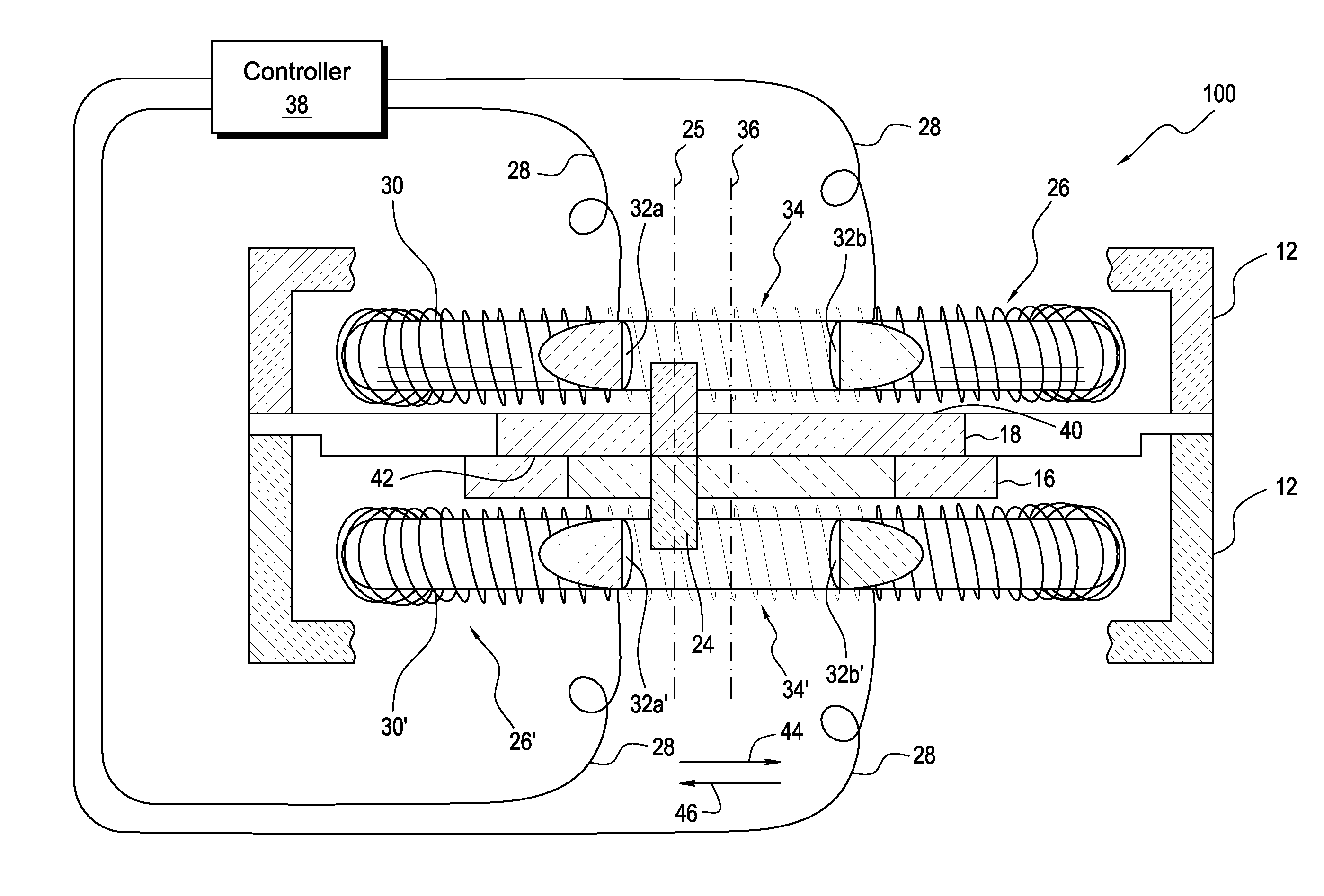
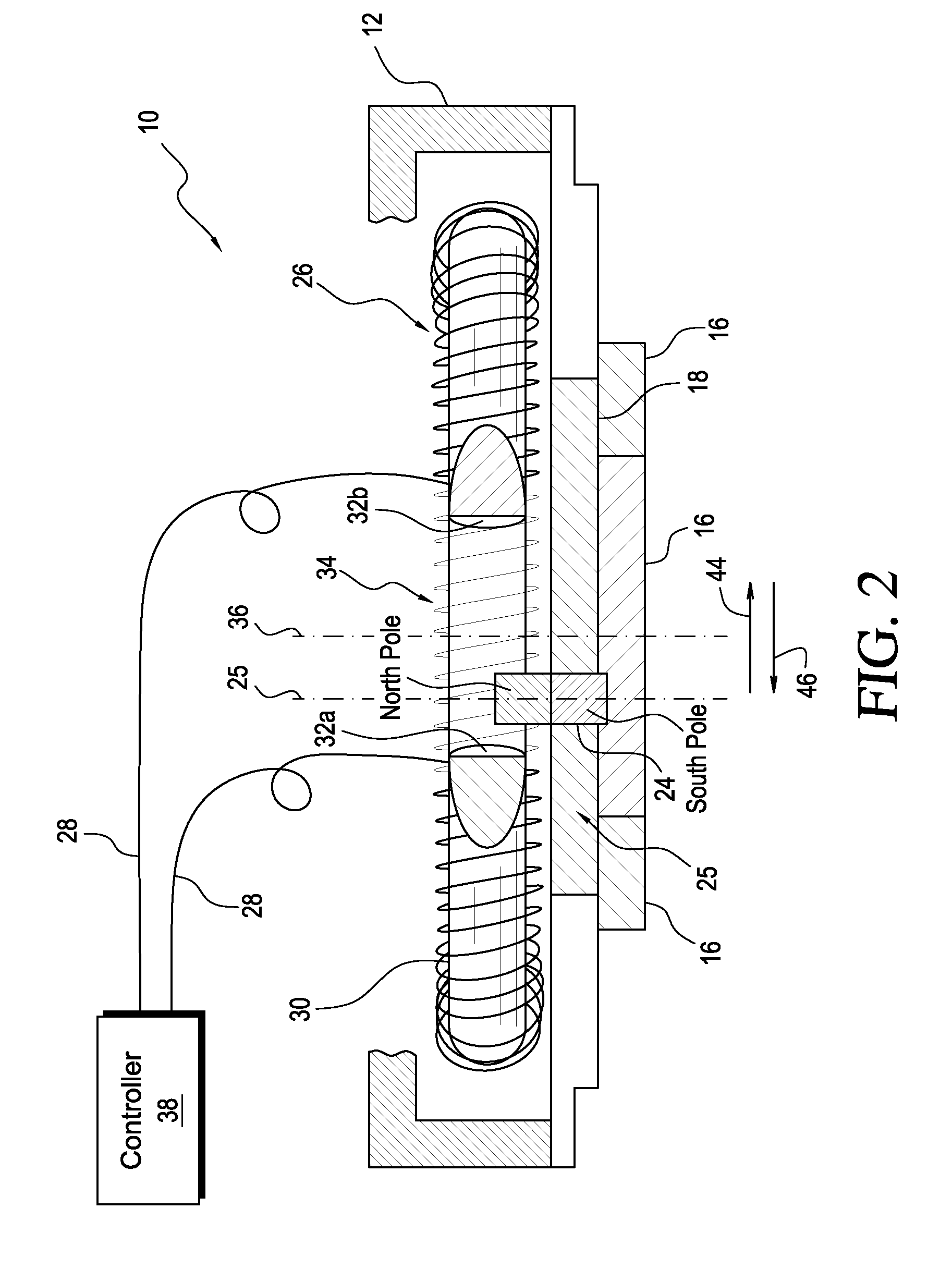
[0030]FIG. 1 shows a shutter 10 according to an exemplary embodiment of the present disclosure. The shutter 10 is a type that can be used in any photographic, scientific or calibration application that requires one or more cycles of opening and closing of a shutter opening by driving one or more shutter blades across an opening.

[0031]The shutter 10 includes a base plate 12 defining a shutter opening 14. In an exemplary embodiment, the shutter opening 14 is a circular aperture having a central axis 36. Light is selectively occluded from passing through and is allowed to pass through the shutter opening 14 by moving a plurality of shutter blades 16 (usually five) in a pivoting action across the shutter opening 14. The shutter blades 16 preferably all move in a single shutter plane, which is normal to the central axis 36 of the shutter opening 14. In prior art shutters, the shutter blades are operated by a linear motor mounted to the base plate. The motor acts through a mechanical link...


PUM


Abstract

A method of controlling a plurality of shutter blades includes providing a shutter assembly including a solenoid having a first magnetic pole, a second magnetic pole, and a gap between the first and second poles. The shutter assembly also includes a permanent magnet moveable within the gap in a path coplanar with the solenoid, wherein movement of the permanent magnet transitions the plurality of shutter blades between an open position exposing a central opening of the shutter assembly and a closed position. The method also includes moving the plurality of shutter blades between the open and closed positions, and reducing an electrical signal applied to the solenoid while the plurality of shutter blades is in transit between the open and closed positions.

Description

CROSS-REFERENCE TO RELATED APPLICATIONS[0001]The present application is a continuation of U.S. patent application Ser. No. 12 / 046,958, filed Mar. 12, 2008, the entire disclosure of which is expressly incorporated herein by reference.BACKGROUND OF THE INVENTION[0002]1. Field of the Invention[0003]The present invention relates generally to shutter assemblies and more particularly to photographic-type shutter assemblies that rely on electromagnetic forces to open and close.[0004]2. Description of Related Art[0005]Electrically operated lens shutters used in various types of photographic and laboratory equipment are well known in the art. Lens shutters especially adapted for high speed opening and closing can operate in fractions of a second. An open / close cycle can take place in 30-40 milliseconds or less and repeated cycles at frequencies of 30 cycles per second are common.[0006]Lens shutters generally are of two types. In one type, a so-called “guillotine” shutter has one or two thin,...

Claims


Application Information

Patent Timeline
IPC IPC(8): G03B9/08
CPCG03B9/08
Inventor VIGLIONE, DAVID
Owner VA INC
Why Eureka
Try Eureka