Proximity detector

a detector and proximity technology, applied in the field of proximity detectors, can solve the problems of reducing the accuracy of the proximity detector, the potential problem of skipping poscomp signal transitions can occur, so as to achieve accurate tracking and reduce signal edge jitter

Active Publication Date: 2007-04-03
ALLEGRO MICROSYSTEMS INC
View PDF15 Cites 111 Cited by
  • Summary
  • Abstract
  • Description
  • Claims
  • Application Information

AI Technical Summary

Benefits of technology

[0014]The proximity detector provides two mode of operation. In a first mode of operation the coarse and fine DACs operate in combination as one higher order DAC. In a second mode of operation, the coarse DAC is provided with one or more extra counts, allowing the tracking signal to move more rapidly to track a rapidly changing magnetic field signal.
[0016]With this particular arrangement, a proximity detector and method for detecting a ferrous article are provided which can accurately track a rapidly changing magnetic field signal and for which signal edge jitter is reduced.

Problems solved by technology

It will also be appreciated that the same potential problem of skipping POSCOMP signal transitions can occur when the DIFF signal has a rapidly decreasing or rapidly increasing amplitude, since the PEAKDAC signal will not have time to catch the DIFF signal before it changes direction.
However, having only eight bits, the conventional proximity detector of FIG. 1 can experience undesirable jitter of the PEAKDAC signal edges, and therefore, undesirable jitter of the POSCOMP signal edges, resulting in reduced accuracy of the proximity detector.

Method used


Image

  • Proximity detector
  • Proximity detector
  • Proximity detector

Examples


Embodiment Construction

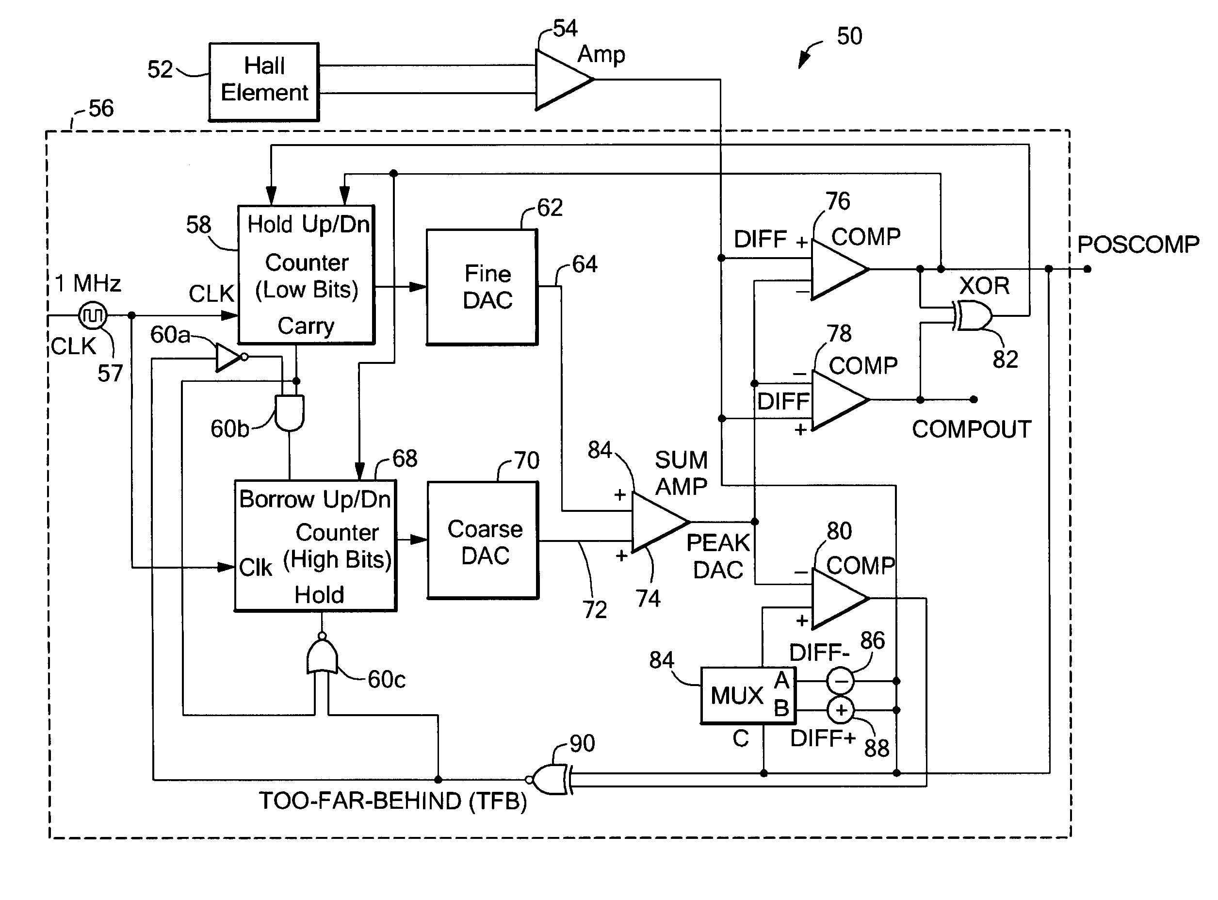
[0025]Referring to FIG. 3, a proximity detector 50 includes a magnetic-field-to-voltage transducer 52 coupled to an amplifier 54, for providing a magnetic field signal, DIFF, indicative of an ambient magnetic field. In one particular embodiment, the magnetic field transducer 52 is a Hall effect element. However, other types of magnetic field transducers can be used with this invention, including but not limited to a magnetoresistive device. The proximity detector 50 also includes a peak detector circuit 56 having a first counter 58 and a fine DAC 62 for providing a first output signal 64 having a first step size, and a second counter 68 and a coarse DAC 70 for providing a second output signal 72 having a second step size larger than the first step size. The peak detector circuit 56 also includes a summation circuit 74 for providing a tracking signal, PEAKDAC, as a sum of the first and second output signals 64, 72, respectively.

[0026]The DIFF signal is coupled to a non-inverting inpu...


PUM


Abstract

A proximity detector includes a fine DAC and a coarse DAC, outputs of which are summed to provide a tracking signal for tracking a magnetic field signal. The proximity detector provides two mode of operation. In a first mode of operation the coarse and fine DACs operate in combination as one higher order DAC. In a second mode of operation, the coarse DAC is provided with one or more extra counts, allowing the tracking signal to move more rapidly to track a rapidly changing magnetic field signal. In another embodiment, the proximity detector also includes an offset circuit for bringing at least one of the magnetic field signal and the tracking signal towards the other one of the magnetic field signal and the tracking signal.

Description

CROSS REFERENCE TO RELATED APPLICATIONS[0001]Not Applicable.STATEMENT REGARDING FEDERALLY SPONSORED RESEARCH[0002]Not Applicable.FIELD OF THE INVENTION[0003]This invention relates to proximity detectors and more particularly to a proximity detector that provides close tracking of a magnetic field signal.BACKGROUND OF THE INVENTION[0004]Proximity detectors for detecting ferrous or magnetic articles are known. One application for such devices is in detecting the approach and retreat of each tooth of a rotating ferrous gear. The magnetic field associated with the ferrous article is detected by a magnetic field-to-voltage transducer, such as a Hall element or a magnetoresistive device, which provides a signal proportional to a detected magnetic field (i.e., a magnetic field signal). The proximity detector processes the magnetic field signal to generate an output signal that changes state each time the magnetic field signal crosses a threshold signal.[0005]In one type of proximity detect...

Claims


Application Information

Patent Timeline
Patent Type & Authority Patents(United States)
IPC IPC(8): G01B7/14
CPCG01V3/081
Inventor SCHELLER, KARLMONREAL, GERARDOSTAUTH, JASON
Owner ALLEGRO MICROSYSTEMS INC
Why Eureka
Try Eureka