Optical tracking apparatus using six degrees of freedom

a technology of optical tracking and apparatus, applied in the field of eye tracking, can solve the problems of increasing system complexity and cost, requiring high-precision instruments and sophisticated data analysis and interpretation, and requiring measurement that is difficult to achieve in practice, so as to improve the appearance of pupils.

Inactive Publication Date: 2011-12-13
KAPLAN ARKADY
View PDF16 Cites 123 Cited by
  • Summary
  • Abstract
  • Description
  • Claims
  • Application Information

AI Technical Summary

Benefits of technology

[0013]One embodiment of the present invention, called hereinafter a first operational mode, invokes more than one off-axis light source in combination with a single camera. The use of at least two glint spots produced by multiple light sources and detected by a single camera significantly improves the robustness of object locking and tracking. A second operational mode employs two cameras and a single off-axis light source, while the other light sources are blocked or switched off. Two glint spots are produced by the same optical source and each spot is detected only by one corresponding camera. This mode enables more accurate object locking and tracking.
[0015]The system may also be applied to eye ball location and orientation tracking and computing a gaze direction (line of sight) in real time. For this purpose, eye features, such as a subject's pupil are treated as object surface marks and used for multi DoF tracking. In yet another embodiment, the cameras may have additional on-axis illumination to intensify the appearance of the pupils.

Problems solved by technology

Adding more cameras helps alleviate performance issues, but further drives up the system complexity and cost.
However, these measurements are difficult to achieve in practice and require high-precision instruments as well as sophisticated data analysis and interpretation.
Despite the number of developed techniques, the concomitant improvement in performance has been rather modest.
Developers are still being challenged by problems related to head-movement, tracker over-sensitivity and / or unreliable calibration.
Some systems require complicated personal calibration procedures, others are based on wearable head-mounted gears, and some restrict the user's head positions within a narrow area.
The drawbacks of these approaches are the need for a separate control unit and the use of bulky transmitters.
In sum, there is still an urgent need for an accurate, unobtrusive, and reliable method and system of real-time gaze-tracking.
However, this method suffered from a low angular resolution and compromised accuracy.
While the robustness of pupil tracking may be improved with this implementation, the problem of head movement compensation remains unresolved.
It is worthwhile to note that despite the obvious advantages of using bright pupil conditions, this type of illumination inherently limits tracking resolution due to a relatively high sensitivity to head movements.
However, the accuracy of this approach is compromised in cases when glints are located close to the optical axis (i.e. the straight line connecting the origin (camera) and object (cornea center)).
Thus, the error increases rapidly with the distance between glints.
While the aforementioned prior art methods are useful advances in the field of eye-gaze tracking, they are adversely affected by short tracking ranges, frequent recalibration, flow stability (frequent floss of tracking) and high cost.
All these deficiencies prevent object / eye trackers from being used by the general public and limit their applications to research laboratories and boutique markets.

Method used


Image

  • Optical tracking apparatus using six degrees of freedom
  • Optical tracking apparatus using six degrees of freedom
  • Optical tracking apparatus using six degrees of freedom

Examples


Embodiment Construction

[0028]The present invention is now described more fully with reference to the accompanying figures, in which some of all possible embodiments of the invention are shown. The present invention may be embodied in various forms and should not be viewed as limited to the embodiments set forth herein. Rather these embodiments are provided so that this disclosure will be thorough and complete and will fully disclose the invention to those skilled in the art.

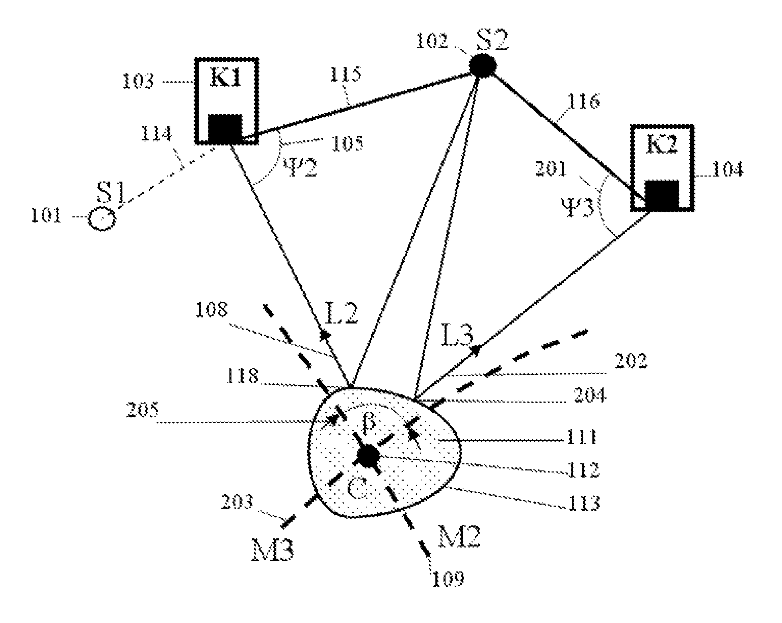
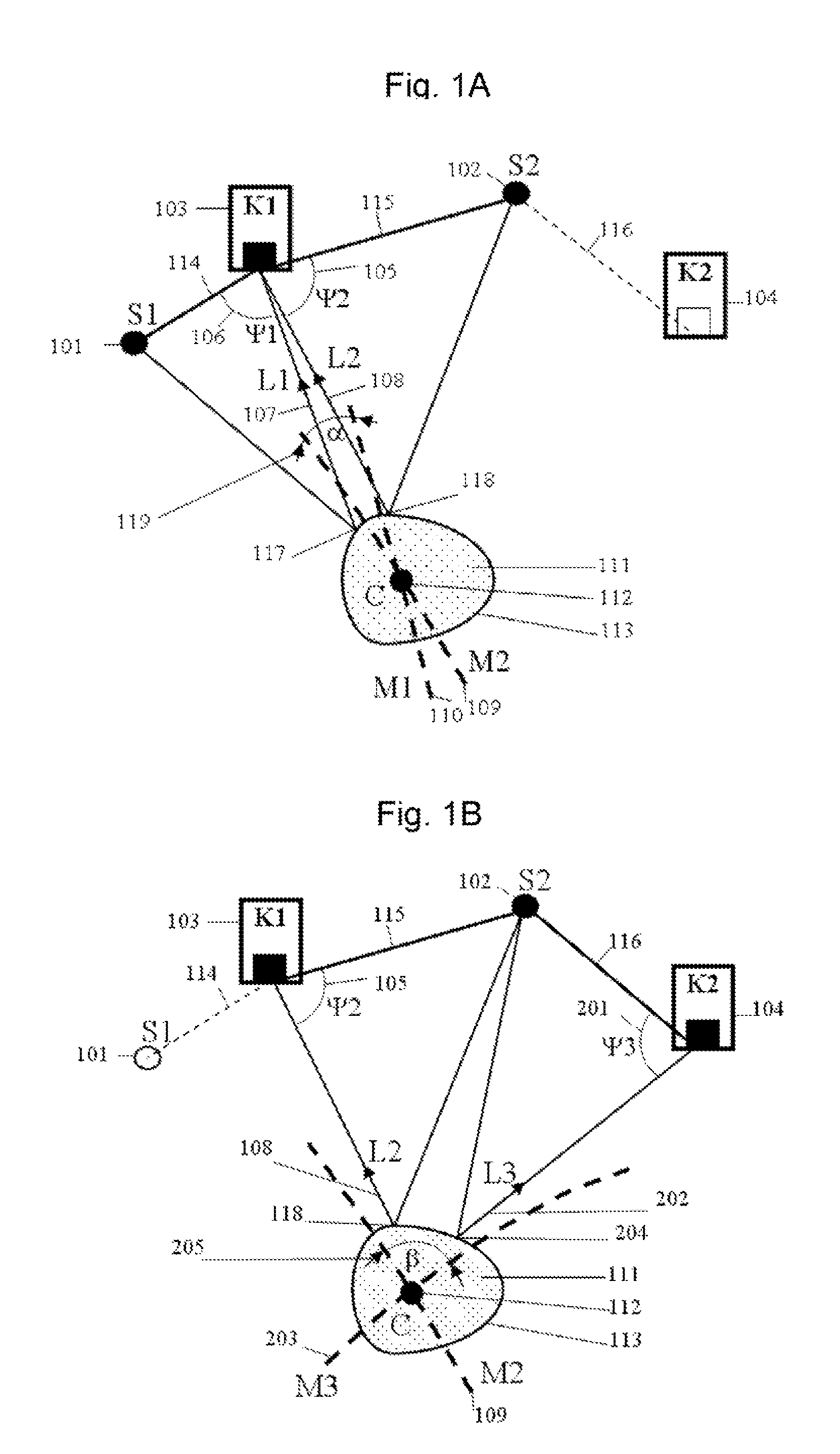
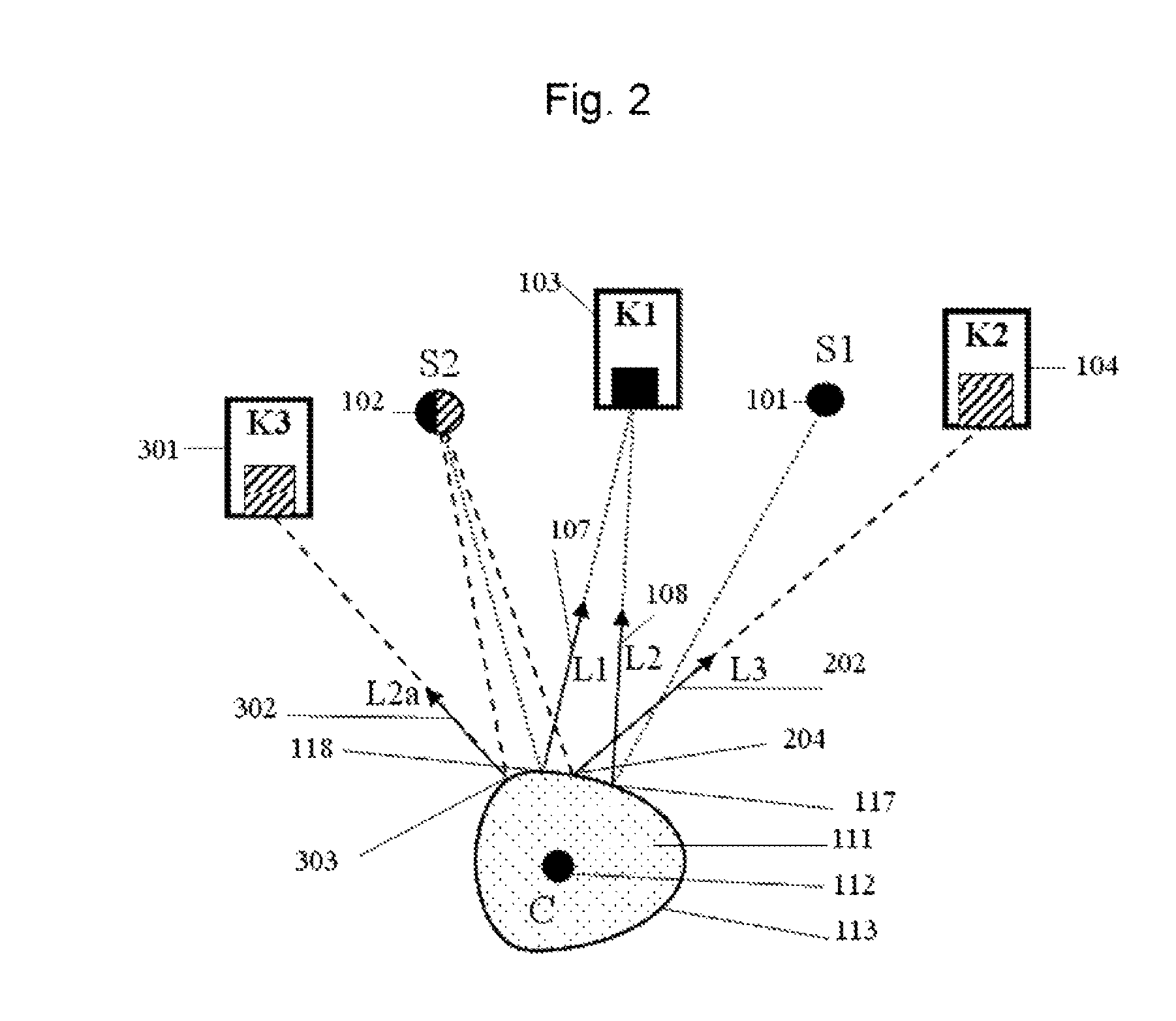
[0029]One preferred embodiment of the invention consists of two off-axis optical sources S1 and S2 and two cameras K1 and K2, as shown in FIG. 1A and FIG. 1B. Such an embodiment is capable of performing the two operational modes in cycles, i.e. one after another. Accordingly, the first operational mode is shown schematically in FIG. 1A, while the second operational mode in FIG. 1B.

[0030]FIG. 1 represents the following elements of the preferred embodiment: S1 and S1 are a first and second light source (101 and 102), respectively; K1 and...


PUM


Abstract

This invention discloses an optical object tracking method and system with to up to six degrees of freedom: three translational and three angular coordinates. In the preferred embodiment, the system includes two near-infra-red light sources (e.g., light emitting diode), two cameras, and a digital signal processor. The system performs to tasks: object locking and tracking. For object locking and tracking, a single camera and two off-axis light sources are engaged. For more precise object tracking, two spatially-separate cameras and a single diode are used. In another embodiment, a third camera may be used to separate the locking and tracking tasks. The light sources may have different light wavelengths and may operate in a sequential mode. The cameras may be sensitive over different spectral ranges and may also differ in terms of field-of-view and resolution. The invention describes a method based on capturing images of light reflections at the camera focal plane and analyzing them, through mathematical mapping, for known locations of light sources and cameras. Invention can be adopted for the tracking of an eyeball. The related method determines an object location and orientation or a gaze vector and a point-of-regard.

Description

RELATED APPLICATIONS[0001]This application claims benefit of the U.S. provisional patent application No. 60 / 835,874 filed Aug. 7, 2006.FIELD OF THE INVENTION[0002]The invention relates generally to an apparatus and method for real-time multi-degree of freedom (DoF) optical tracking, which determines the location of an object with a single camera and further performs precise tracking of the object by a pair of cameras. More particularly, invention relates to eye tracking and determines a point of gaze (line of sight).BACKGROUND OF THE INVENTION [0003]Optical motion capture systems are typically based on high contrast video imaging of retro-reflective markers, which are attached to strategic locations on an object. The markers are usually spherical objects or disks ranging from 1 to 5 cm in diameter, depending on the motion capture hardware and the size of the active area, and are sometimes covered by reflective materials. Some markers may incorporate infra-red (IR) light emitting dio...

Claims


Application Information

Patent Timeline
Patent Type & Authority Patents(United States)
IPC IPC(8): G06K9/00A61B3/14
CPCA61B3/113A61B3/14G06K9/00604G06F3/013G06V40/19
Inventor KAPLAN, ARKADY
Owner KAPLAN ARKADY
Why Eureka
Try Eureka