Connection system

Inactive Publication Date: 2009-09-17
HON HAI PRECISION IND CO LTD
View PDF7 Cites 38 Cited by
  • Summary
  • Abstract
  • Description
  • Claims
  • Application Information

AI Technical Summary

Benefits of technology

[0006]What is desired, therefore, is to provide a connection system which can simultaneously connect a plurality of slave devices.

Problems solved by technology

However, this conventional connection system only allows the master device to connect with one of the slave devices at any given time via the serial interfaces thereof.
If the master device needs to access another slave device at the same time, the user must connect a serial interface of the master device to a serial interface of another slave device again, which can be very inconvenient.

Method used


Image

  • Connection system
  • Connection system
  • Connection system

Examples


Embodiment Construction

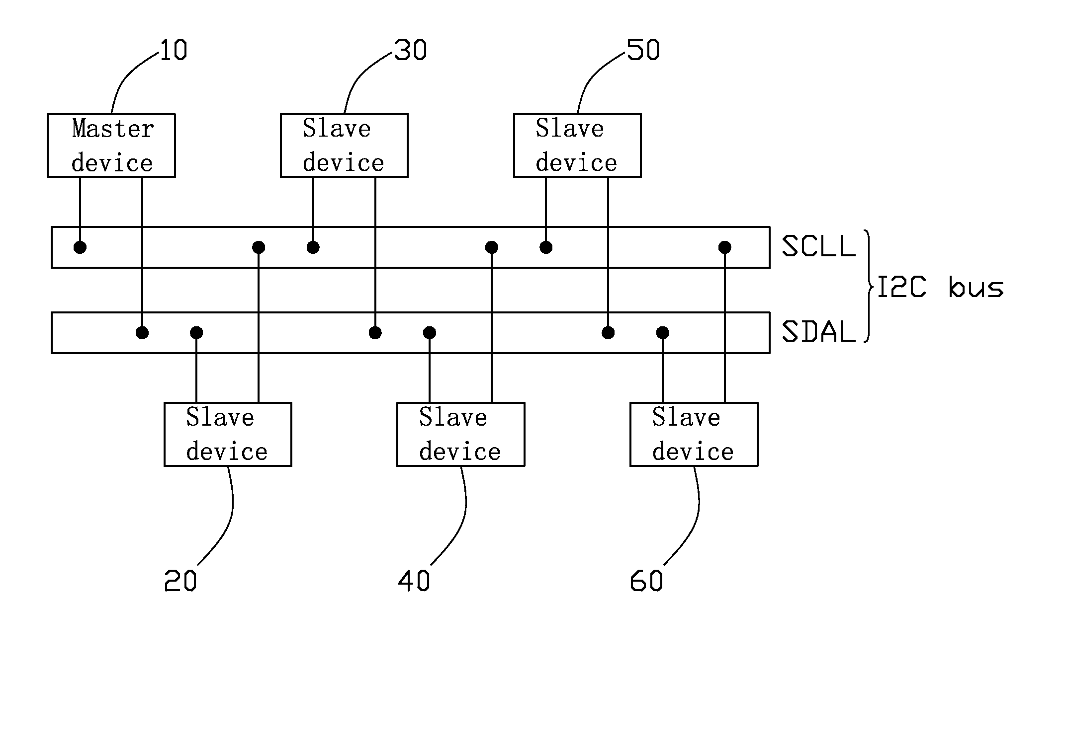
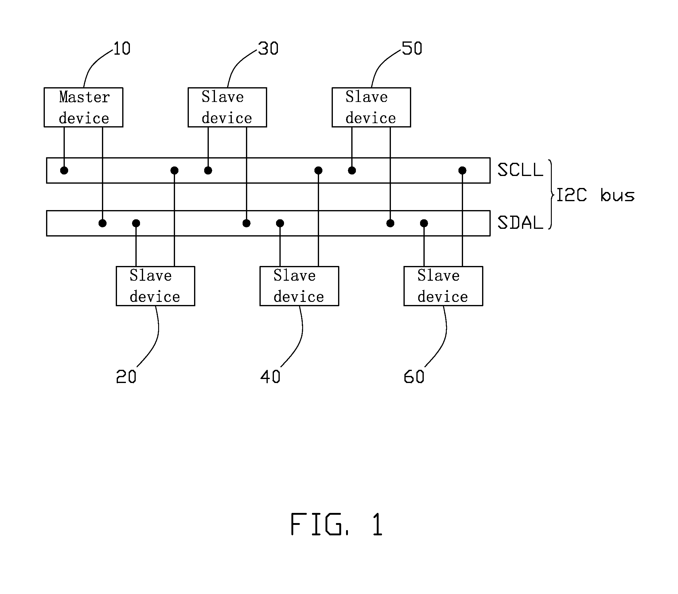
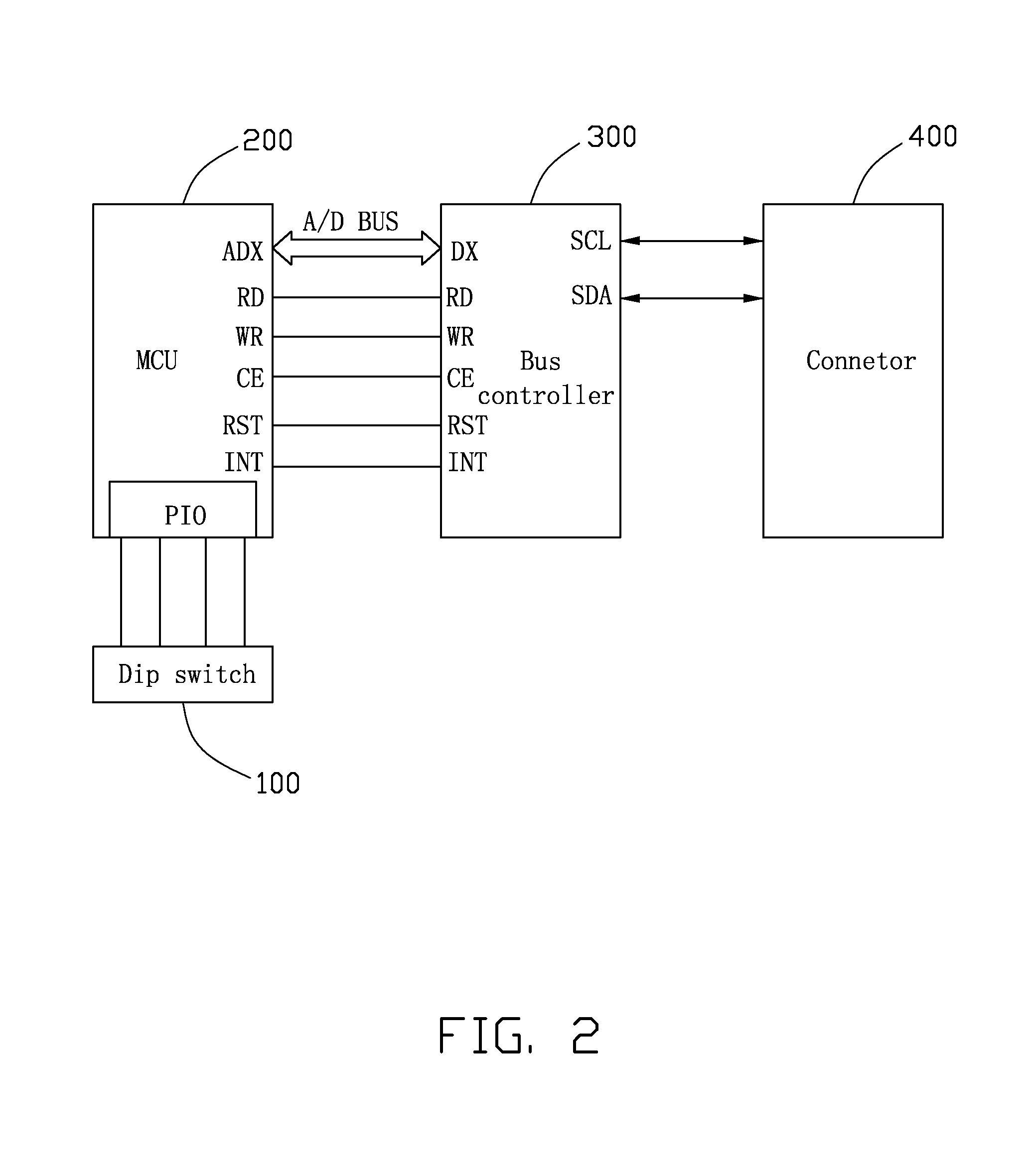
[0011]Referring to FIG. 1 and FIG. 2, a connection system in accordance with an embodiment of the present invention includes an inter-integrated circuit (I2C) bus, a master device 10, such as a server, and five slave devices 20-60, such as uninterrupted power supply (UPS) systems. The master device 10 and slave devices 20-60 all have a similar structure. The master device 10 includes a dip switch 100, a micro controller unit (MCU) 200, a bus controller 300, and a connector 400. In other embodiments, the number of slave devices can be varied according to user-specific needs.

[0012]The MCU 200 includes a plurality of input / output (I / O) ports PIO, a plurality of address / data pins ADX, and five control pins RD, WR, CE, RST, INT. The bus controller 300 includes a plurality of address / data pins DX, five control pins RD, WR, CE, RST, INT, a serial clock pin SCL, and a serial data pin SDA. The dip switch 100 is connected to the I / O ports PIO of the MCU 200 and is configured for assigning an ...


PUM


Abstract

An exemplary connection system includes an I2C bus and two or more devices. Each device has a dip switch, a MCU, and a bus controller. The dip switch is configured for assigning an address to the device. The MCU is connected to the dip switch and configured for detecting whether the device is a master or a slave device according to the address assigned by the dip switch. The bus controller is connected to the MCU and the I2C bus, and is configured for converting a data transmission mode between the MCU and the bus controller. In this system, at least one device is a master device and at least one device is a slave device, the master device is capable of monitoring the slave device, and the slave device is capable of transmitting information to the master device.

Description

BACKGROUND[0001]1. Field of the Invention[0002]The present invention relates to a connection system, and particularly to a connection system for connecting a plurality of electronic devices.[0003]2. Description of Related Art[0004]In a conventional connection system for connecting a plurality of electronic devices, serial interfaces are used for data communications between a master device and a plurality of slave devices.[0005]However, this conventional connection system only allows the master device to connect with one of the slave devices at any given time via the serial interfaces thereof. If the master device needs to access another slave device at the same time, the user must connect a serial interface of the master device to a serial interface of another slave device again, which can be very inconvenient.[0006]What is desired, therefore, is to provide a connection system which can simultaneously connect a plurality of slave devices.SUMMARY[0007]An exemplary connection system i...

Claims


Application Information

Patent Timeline
Patent Type & Authority Applications(United States)
IPC IPC(8): G06F13/18
CPCG06F13/4291G06F2213/0052G06F2213/0016
Inventor KUO, HENG-CHEN
Owner HON HAI PRECISION IND CO LTD
Why Eureka
Try Eureka