Method For The Operation Of A Rolling Mill Used For Milling A Strip-Shaped Rolling Stock

a technology of strip-shaped rolling stock and rolling mill, which is applied in the direction of rare end control device, roll mill control device, manufacturing tools, etc., can solve the problems of reducing the amount of usable rolling stock, reducing the yield, and consuming time for rolling stock alignment, so as to achieve the effect of increasing productivity and yield

Inactive Publication Date: 2009-09-24
PRIMETALS TECH GERMANY
View PDF7 Cites 9 Cited by
  • Summary
  • Abstract
  • Description
  • Claims
  • Application Information

AI Technical Summary

Benefits of technology

[0010]The object of the present invention is to improve a method for operation of a rolling ...

Problems solved by technology

Both effects reduce what is known as yield, meaning the proportion of usable rolling stock volume.
The alignment of the rolling stock is time-consuming and has a negative influence on the productivity of the rolling mill.
In addition only a poor alignment is possible, especially when the strip-shaped rolling stock has a large width-to-length ratio.
In addition there is the danger, even with correct alignment of the rolling stock, that the rolling stock will twist again between alignment b...

Method used


Image

  • Method For The Operation Of A Rolling Mill Used For Milling A Strip-Shaped Rolling Stock
  • Method For The Operation Of A Rolling Mill Used For Milling A Strip-Shaped Rolling Stock
  • Method For The Operation Of A Rolling Mill Used For Milling A Strip-Shaped Rolling Stock

Examples


Embodiment Construction

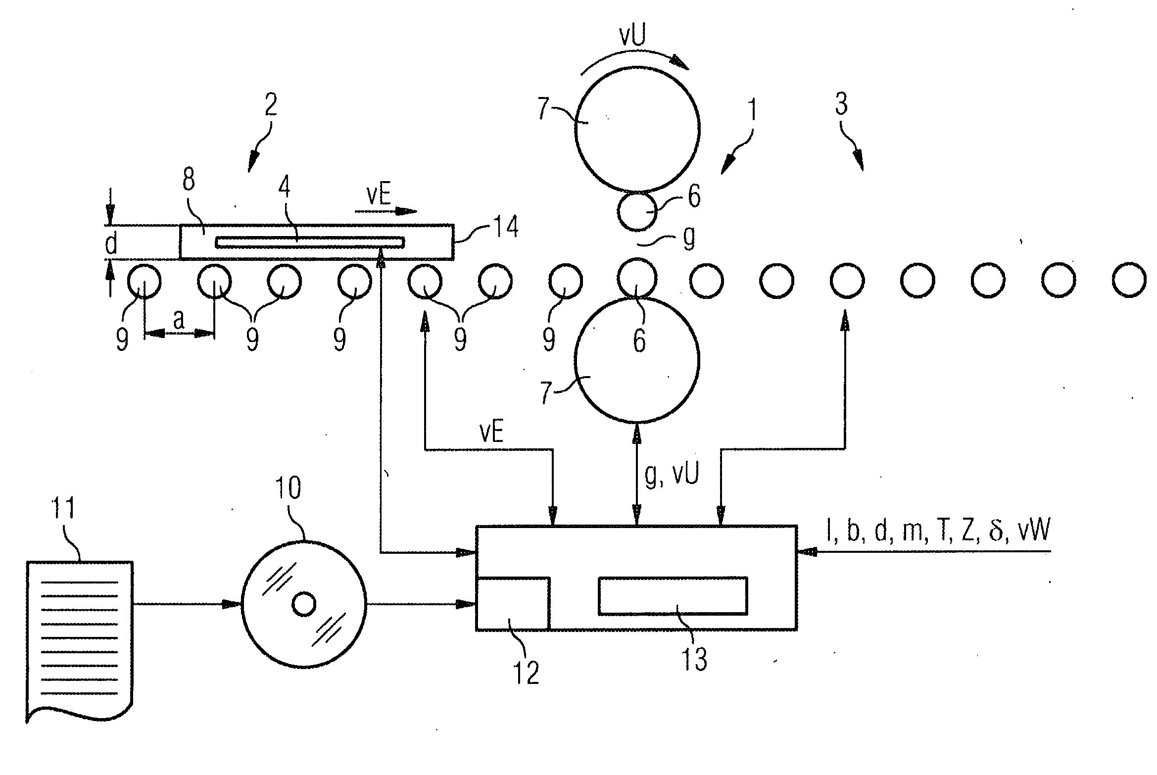
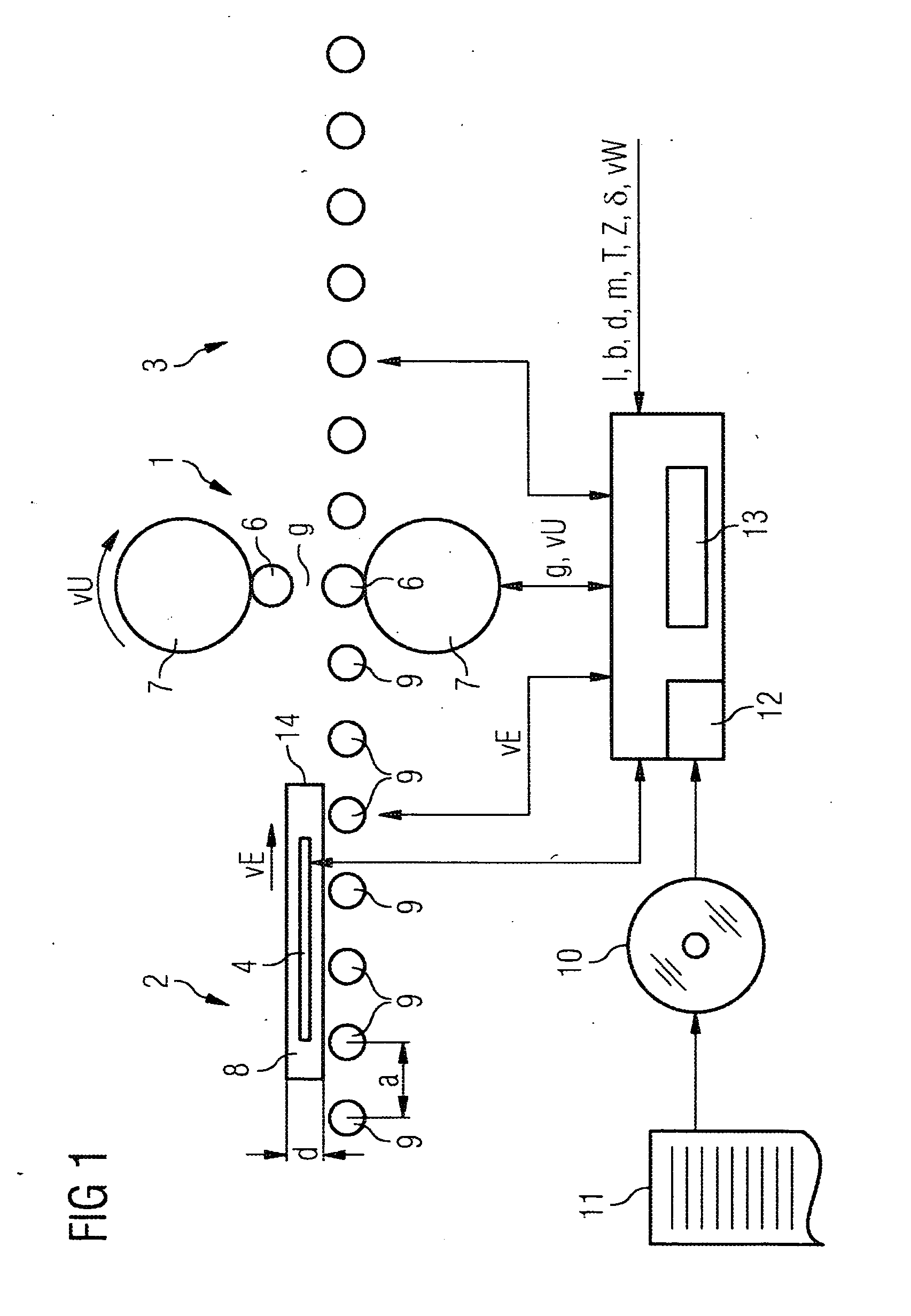
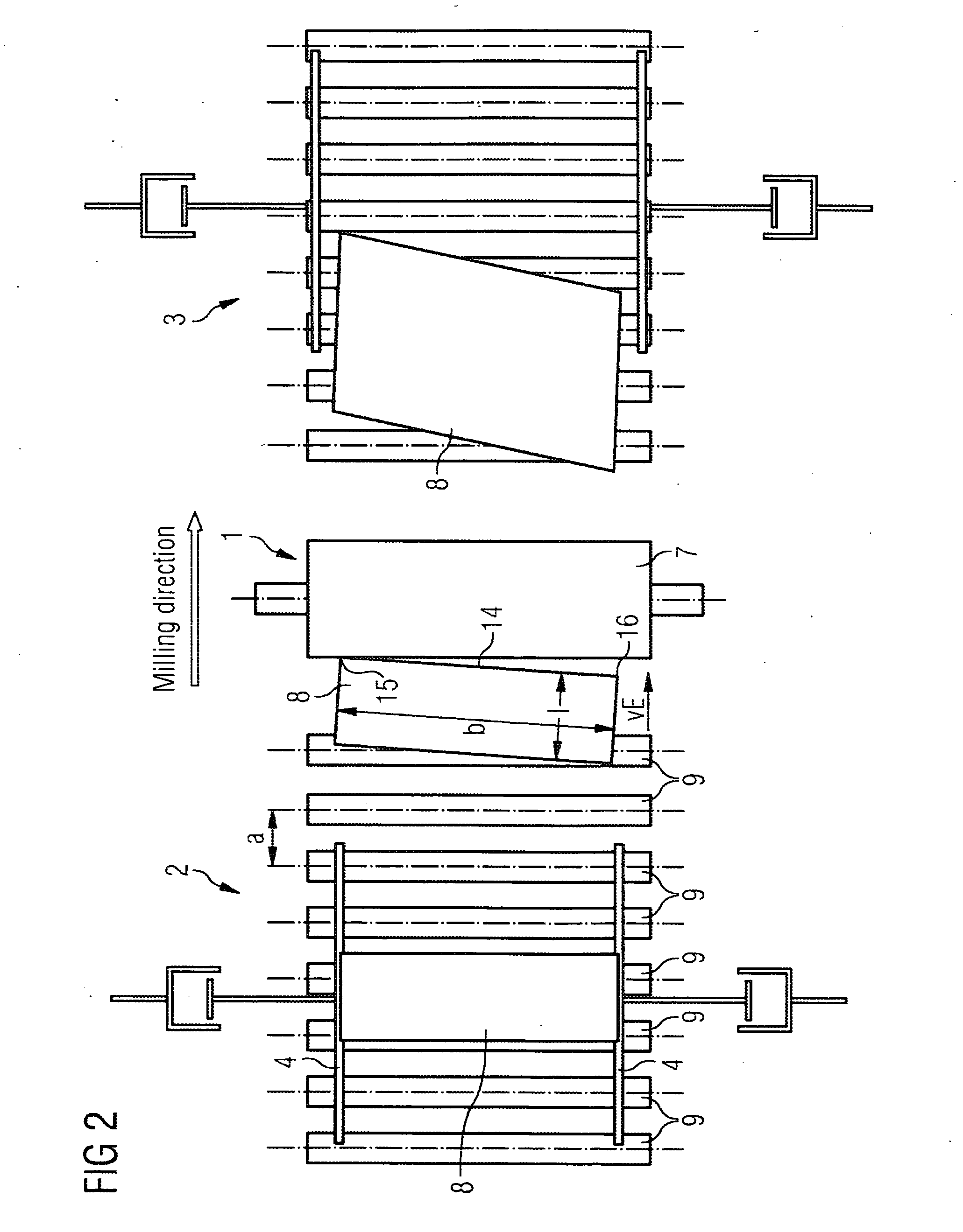
[0028]In accordance with FIGS. 1 and 2 a rolling mill features a roll stand 1, two roll trains 2, 3, material guides 4 and a control device 5. The roll stand 1 features at least two working rolls 6, as a rule further rolls 7 as well, for example two support rolls 7.

[0029]The rolling mill is used for milling a strip-shaped rolling stock 8. One of the two roll trains 2, 3 is arranged on the feeding side and the output side of the roll stand 1 respectively. The roll trains 2, 3 each feature a number of transport rolls 9 spaced at a distance from one another. The material guides 4 are arranged on the entry-side roll train 2. They are able to be laterally adjusted to the rolling stock 8. The control device 5 is used to control and coordinate the roll stand 1, the material guides 4 and the transport rolls 9 of the roll trains 2, 3.

[0030]This computer program 11 is fed to the control device 5 via a data medium 10, on which a computer program 11 is stored. The control device 5 receives the ...


PUM

PropertyMeasurementUnit
Lengthaaaaaaaaaa
Speedaaaaaaaaaa
Widthaaaaaaaaaa

Abstract

Disclosed is a rolling mill comprising a roll stand with working rolls, a roll train located at the feeding end of the roll stand, and a control device. The working rolls form a roll gap. The control device triggers the roll stand such that the working rolls rotate at a certain peripheral speed while triggering the roll train located at the feeding end of the roll stand in such a way that the leading edge of the strip-shaped rolling stock reaches the roll gap at a feeding speed that is greater than the peripheral speed. The control device adjusts the peripheral speed and the feeding speed to each other in such a way that a potential angled position of the leading edge relative to the roll gap is at least reduced as a result of said adjustment.

Description

CROSS REFERENCE TO RELATED APPLICATIONS[0001]This application is the US National Stage of International Application No. PCT / EP2007 / 050985, filed Feb. 1, 2007 and claims the benefit thereof. The International Application claims the benefits of German application No. 10 2006 011 975.4 filed Mar. 15, 2006, both of the applications are incorporated by reference herein in their entirety.FIELD OF INVENTION[0002]The present invention relates to a method for the operation of a rolling mill used for milling a strip-shaped rolling stock that is provided with a leading edge with two ends. The rolling mill comprises a roll stand with working rolls, a roll train located at the feeding end of the roll stand and a control device. The working rolls form a roll gap. The control device triggers the roll stand such that the working rolls of the roll stand rotate with a certain peripheral speed. The control device further triggers the roll train located at the feeding end of the roll stand so that the ...

Claims


Application Information

Patent Timeline
IPC IPC(8): B21B37/00
CPCB21B37/00B21B37/68B21B37/72B21B2275/06B21B2273/04B21B2273/14B21B2275/04B21B39/12
Inventor SCHMIDT, BIRGER
Owner PRIMETALS TECH GERMANY
Why Eureka
Try Eureka