
Positioning shoe retainer assembly of bicycle

a technology for bicycles and retainers, applied in the field of bicycles, can solve the problems of insufficient structure and need for screws

Inactive Publication Date: 2009-09-24
CHEN CHUNG I
View PDF3 Cites 3 Cited by
  • Summary
  • Abstract
  • Description
  • Claims
  • Application Information

AI Technical Summary

Benefits of technology

[0006]Accordingly, the object of the present invention is to provide a positioning shoe retainer assembly of a bicycle, wherein no screw is used in assembly the shoe retainer 1 to the pedal 2. Thus the user does not need to change the pose in assembly.
[0007]To achieve above object, the present invention provides a positioning shoe retainer assembly of a bicycle comprising a shoe retainer and a pedal. The shoe retainer has a retaining portion. The retaining portion is installed with at least one engaging hole for retaining; an arc portion extending from the retaining portion; an inner side of the arc portion being formed with a receiving portion; the arc portion extending with a combining portion; the combining seat being installed with a combining seat; at least one combining unit extending from the combining seat. The pedal serves to assembled with a bicycle by connecting to a shaft of a bicycle. A surface of the pedal adjacent to the shaft is an inner lateral surface; and a surface of the pedal opposite to the inner lateral surface is an outer lateral surface. An upper surface of the pedal is formed as a treaded surface for being treaded by users. Two lateral surfaces are vertical to the treaded surface, the inner lateral surface and the outer lateral surface. The pedal is formed with at least one combining groove near the lateral surface. In assembly, the shoe retainer is embedded into the combining groove of the pedal by using the combining unit so that the combining seat of the shoe retainer adheres upon the lateral surface of the pedal and the shoe retainer can separate from the pedal from a direction opposite to the direction that the shoe retainer embedded into the pedal. Thus, by the shoe retainer being movably installed to the pedal, the shoe retainer can be assembled and detached rapidly.
[0008]The prior art shoe retainer needs screws to locking the shoe retainer to the pedal or needs press sheets to pass through the pedal for assembly. Even some manufacturers improve the shoe retainer to be installed to the pedal by using hollow retaining posts, but the structure is insufficient and thus screws are necessary. The combining unit has slit and thus it is elastic. Two sides of the combining unit have positioning blocks for resisting against the walls of the combining groove. The combining groove is formed in the treaded surface or lateral surface. In use, the user only need wear the shoe retainer on the foot and then treads the pedal without needing to bend down or to squat. If the shoe retainer is not used or needs to separate from the pedal urgently, the user's foot and the shoe retainer draw from the pedal along a direction opposite to the assembly direction. In the third embodiment of the present invention, the combining unit has a dovetail shape which is assembled to the combining groove from an outer lateral surface to the inner lateral surface so as to be assembled to the combining groove. The detaching work is performed along an opposite direction. It does not affect the riding operation and the riding pose is unnecessary to be changed. Moreover, no screw is used in assembly the shoe retainer to the pedal in the present invention so that the cost is saved.

Problems solved by technology

Even some manufacturers improve the shoe retainer to be installed to the pedal by using hollow retaining posts, but the structure is insufficient and thus screws are necessary.

Method used


Image

  • Positioning shoe retainer assembly of bicycle
  • Positioning shoe retainer assembly of bicycle
  • Positioning shoe retainer assembly of bicycle

Examples


Embodiment Construction

[0015]In order that those skilled in the art can further understand the present invention, a description will be provided in the following in details. However, these descriptions and the appended drawings are only used to cause those skilled in the art to understand the objects, features, and characteristics of the present invention, but not to be used to confine the scope and spirit of the present invention defined in the appended claims.

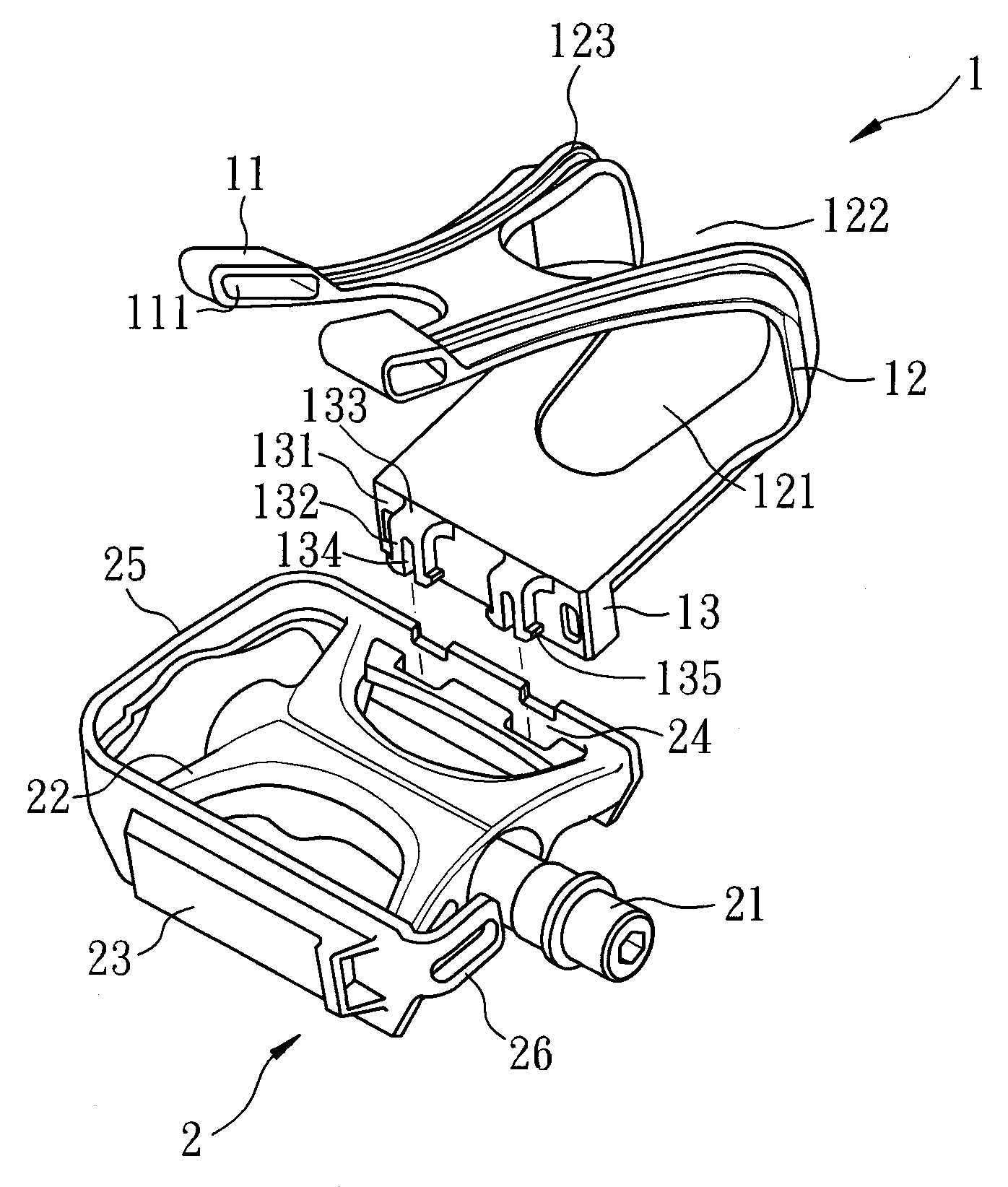
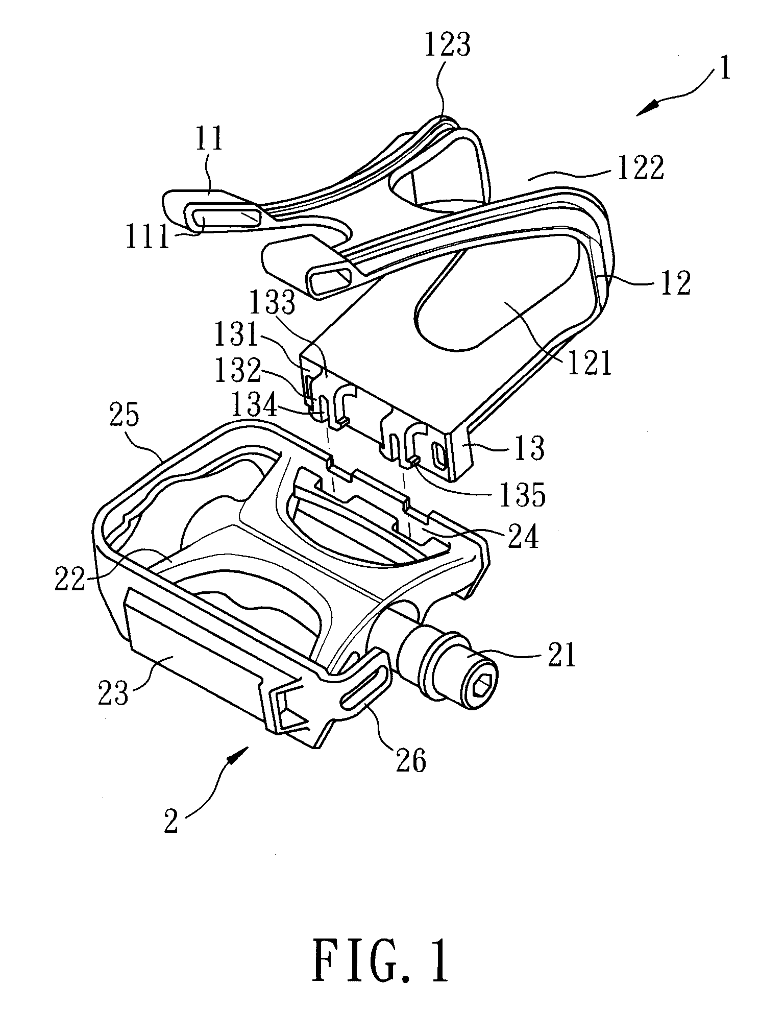
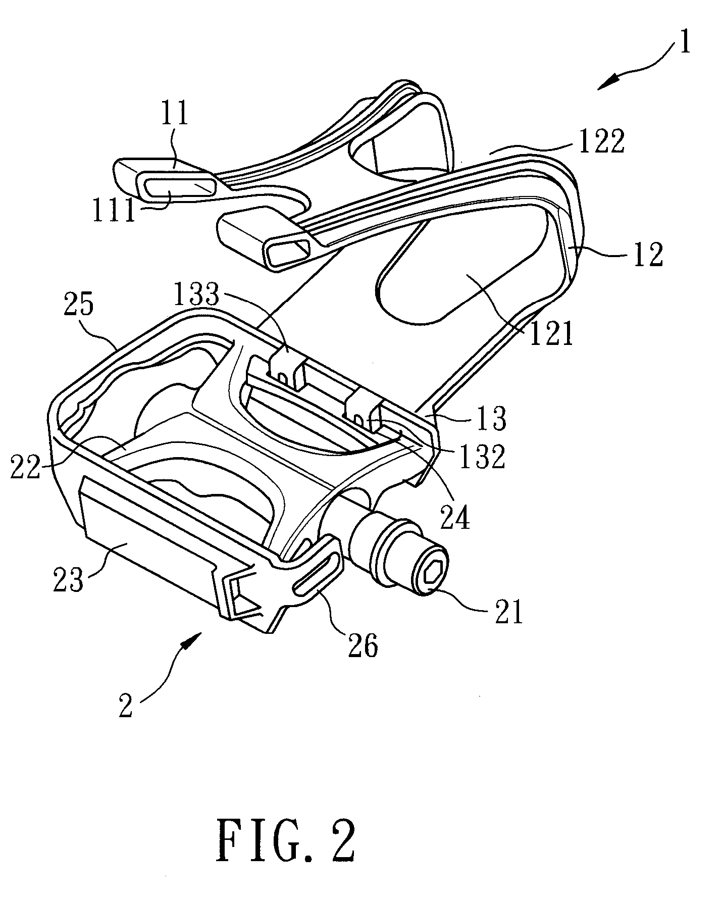
[0016]A shoe retainer assembly for a bicycle, as illustrated in FIGS. 1 and 2 includes a shoe retainer 1 and a pedal 2.

[0017]The shoe retainer 1 has a U shape structure. A bottom of the shoe retainer 1 is installed with a combining portion 13. The combining portion 13 extends upwards to form with an arc portion 12. The arc portion 12 has a receiving groove 122 so as to divide the arc portion 12 into two parts. The upper portion of the arc portion 12 is formed as two retaining portions 11. A distal end of each retaining portion 11 is formed with an ...


PUM


Abstract

A positioning shoe retainer assembly of a bicycle comprises a shoe retainer and a pedal. The shoe retainer has a retaining portion which is installed with at least one engaging hole for retaining. An arc portion is extending from the retaining portion; an inner side of the arc portion being formed with a receiving portion. The arc portion is extending with a combining portion. The combining seat is installed with a combining seat. At least one combining unit is extending from the combining seat 131. The pedal serves to assembled with a bicycle by connecting to a shaft of a bicycle. A surface of the pedal adjacent to the shaft is an inner lateral surface; and a surface of the pedal opposite to the inner lateral surface being an outer lateral surface. An upper surface of the pedal is formed as a treaded surface for being treaded by users.

Description

FIELD OF THE INVENTION[0001]The present invention relates to bicycles, and particularly to a positioning shoe retainer assembly of a bicycle which can be actively assembled to or detached from a pedal without needing any screws.BACKGROUND OF THE INVENTION[0002]Currently riding bicycle has become a popular exercise and is widely accepted by people. To make the driver steadily drive the bicycle without sliding out of the pedals and thus inducing some dangerous conditions or fail in competition, the pedal of a bicycle is installed with a toe retainer which is used with special pedal shoe. However this is inconvenient to the driver. Thus the shoe retainer is developed to improve the prior art defect.[0003]In Taiwan Patent No. “Leg retainer assembly of a bicycle”, in that the leg retainer has a front portion for receiving a front end of a foot and a connecting portion extending from a lower end of the front portion for connecting with the pedal of a bicycle. The leg retainer is extended ...

Claims


Application Information

Patent Timeline
Patent Type & Authority Applications(United States)
IPC IPC(8): B62M3/08
CPCY10T74/217B62M3/086
Inventor CHEN, CHUNG-I
Owner CHEN CHUNG I
Learn More