Filtering Device To Filter The Air Taken In By A Cleaning Apparatus

Inactive Publication Date: 2009-09-24
UNITEKNO
View PDF17 Cites 1 Cited by
  • Summary
  • Abstract
  • Description
  • Claims
  • Application Information

AI Technical Summary

Benefits of technology

[0018]The filtering device according to the present invention allows to perform a progressive double filtering in a single cont

Problems solved by technology

However, this known filtering device has the disadvantage that it has a relatively low filtering capacity.
However, the known double filtering device, although it offers a greater filtering capacity compared with known devices with

Method used


Image

  • Filtering Device To Filter The Air Taken In By A Cleaning Apparatus
  • Filtering Device To Filter The Air Taken In By A Cleaning Apparatus
  • Filtering Device To Filter The Air Taken In By A Cleaning Apparatus

Examples


Embodiment Construction

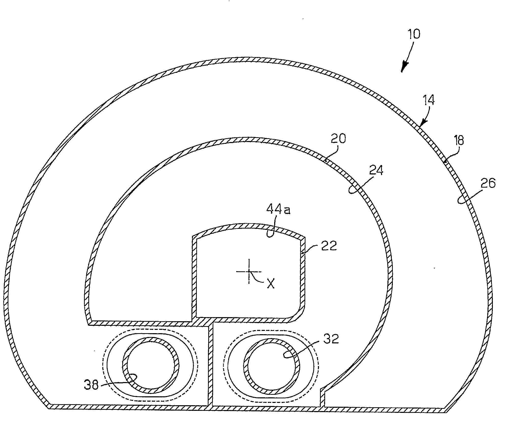
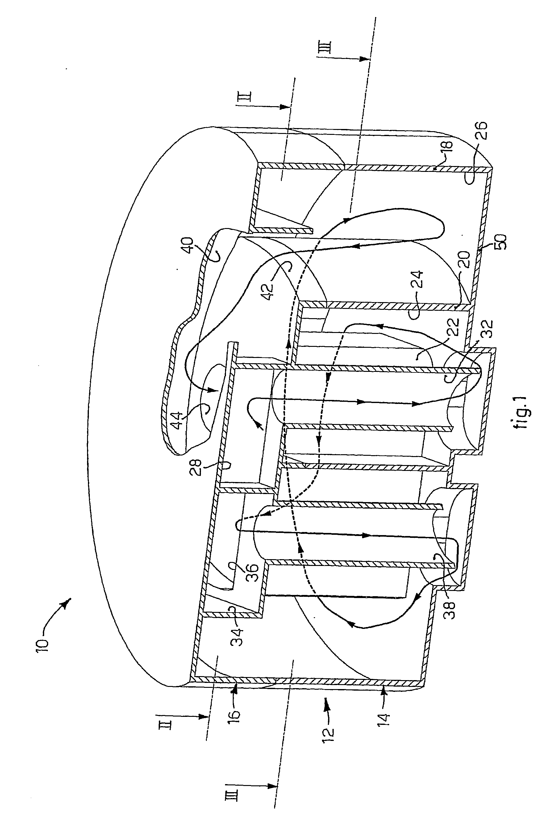
[0029]With reference to FIG. 1, a filtering device 10 according to the present invention can be used to filter, in a liquid bath, the air taken in by a cleaning apparatus.

[0030]The filtering device 10 comprises a container 12, provided with a lower part 14, which functions as a base, and an upper part 16, which functions as a lid.

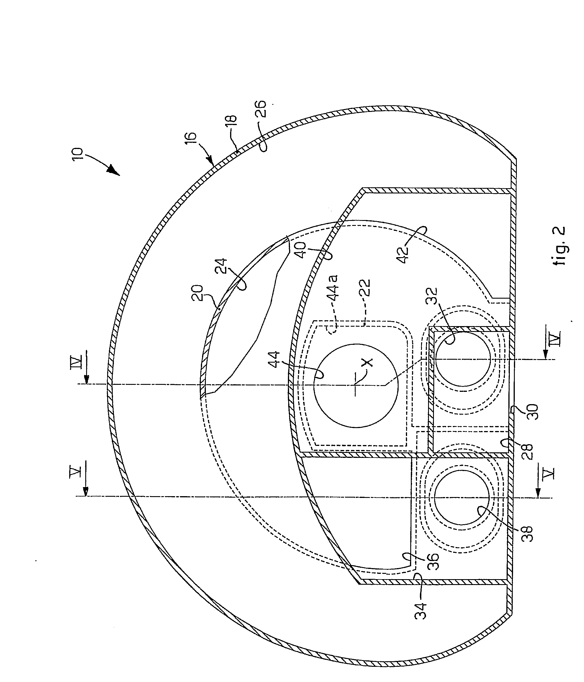
[0031]The container 12 (FIGS. 1 to 5) comprises an outer wall 3018, an intermediate wall 20 and an inner wall 22, walls which have a substantially arched shape, and are substantially parallel and coaxial with each other with respect to an axis X (FIGS. 2, 3 and 4).

[0032]The inner wall 22 and the intermediate wall 20 define a first containing compartment 24, having a partly annular shape.

[0033]The intermediate wall 20 and the outer wall 18 define a 5 second containing compartment 26, outside with respect to the first compartment 24 and disposed adjacent and coaxial with the first containing compartment 24 with respect to the axis X.

[0034]The two containing c...


PUM

PropertyMeasurementUnit
Shapeaaaaaaaaaa

Abstract

Filtering device for filtering the air taken in by a cleaning apparatus, comprising a container provided with a plurality of walls. The walls define at least a first containing compartment, able to contain a first filtering element and in which the air to be filtered is able to be introduced through an inlet pipe, and a second containing compartment, able to contain a second filtering element and connected to the first containing compartment by means of an intermediate pipe, and from which the filtered air is able to exit through a discharge pipe. The two containing compartments are disposed on inside the other, so that the innermost containing compartment is at least partly surrounded by the filtering element contained in the outermost containing compartment.

Description

FIELD OF THE INVENTION[0001]The present invention concerns a filtering device to filter the air taken in by a cleaning apparatus by means of filtering elements, for example of the liquid bath type, or dry. To be more exact, the filtering elements are disposed in relative containing compartments, communicating with each other, and allow to retain the dirt, for example present in the air taken in, so as to separate the dirt from the air.BACKGROUND OF THE INVENTION[0002]Filtering devices are known, for example of the liquid 15 bath type, normally water, which are used in cleaning apparatuses, such as vacuum cleaners, or the so-called vacuum cleaners for liquid.[0003]A filtering device is known comprising a container which defines a containing compartment containing the water, and which is provided with an inlet pipe for the air to be filtered and a discharge pipe for the filtered air. Intake members are provided, which generate an intake flow from the inlet pipe to the discharge pipe i...

Claims


Application Information

Patent Timeline
IPC IPC(8): B01D47/02
CPCA47L9/181A47L9/185B01D47/021B01D46/0039B01D46/0024B01D46/64
Inventor BARTOLINI, VILLELMO
Owner UNITEKNO
Why Eureka
Try Eureka