

Multiple Spring Subsurface Safety Valve
a safety valve and spring technology, applied in the direction of fluid removal, sealing/packing, borehole/well accessories, etc., can solve the problem of reducing the flow and achieve the effect of maximizing the cross-sectional area of the flow tub
- Summary
- Abstract
- Description
- Claims
- Application Information
AI Technical Summary
Benefits of technology
Problems solved by technology
Method used
Image

Examples
Embodiment Construction
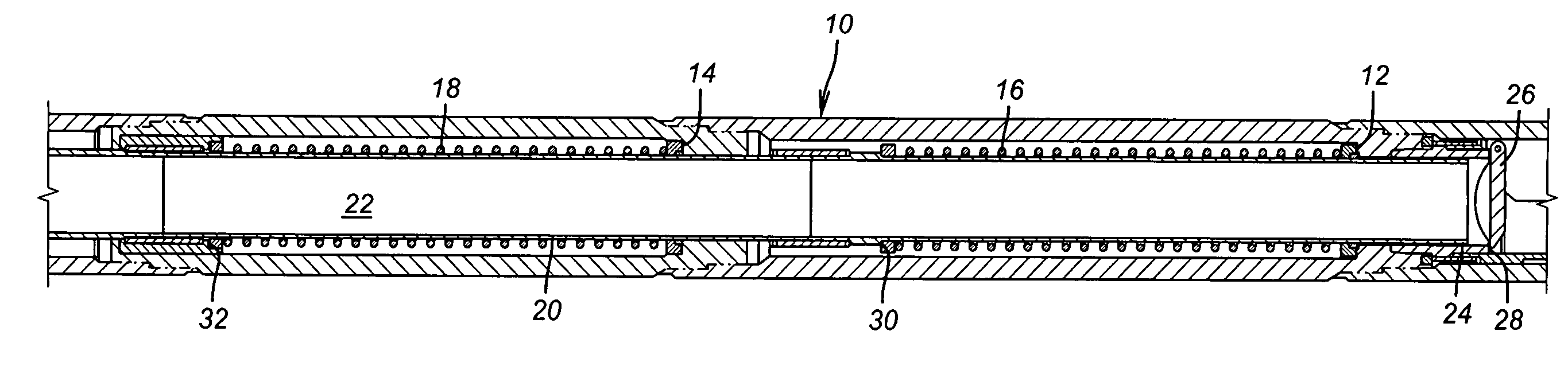
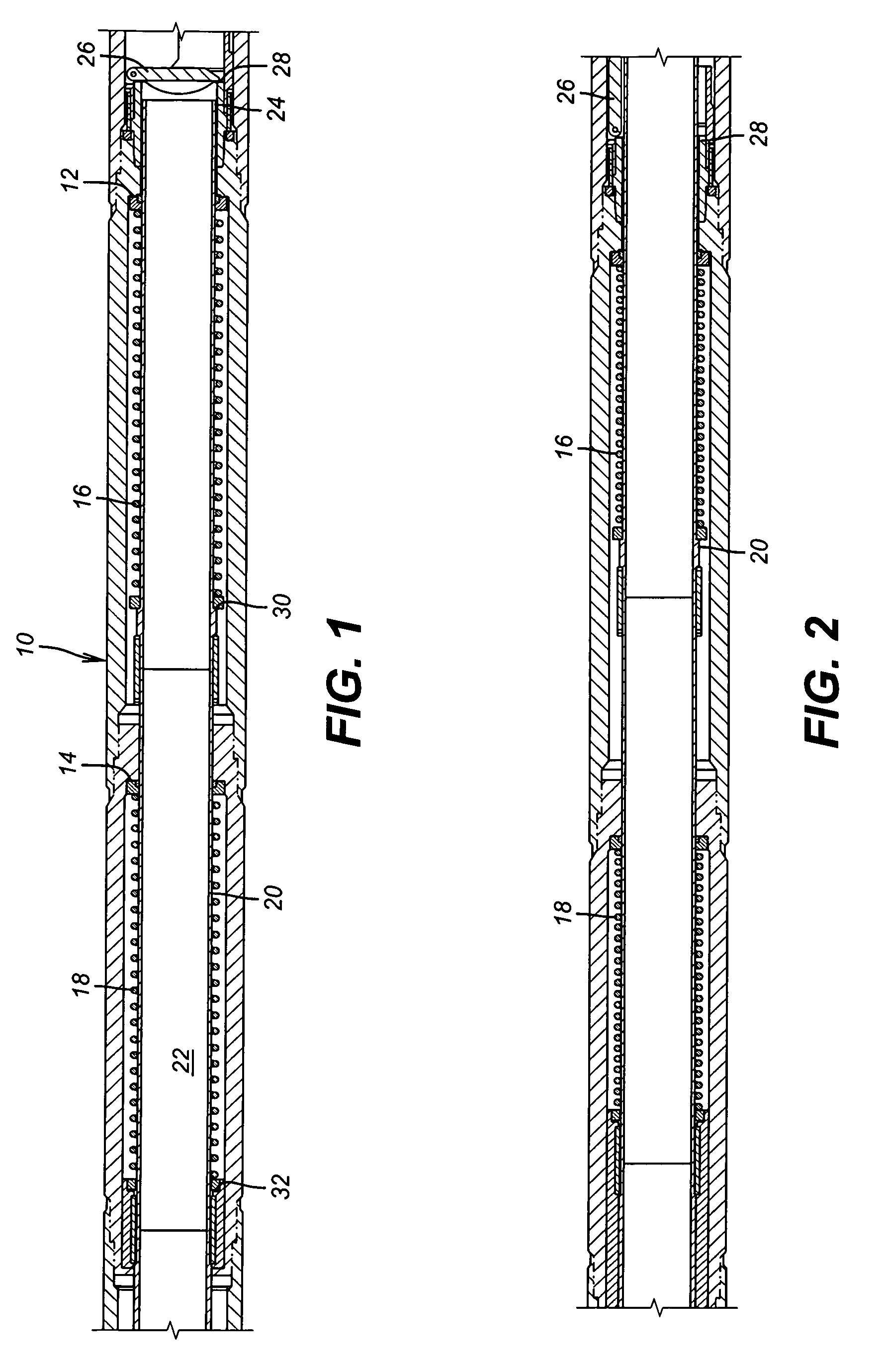
[0008]FIG. 1 shows a housing assembly 10 with supports 12 and 14 on which springs 16 and 18 respectively bear. A flow tube 20 has a passage 22 through it and a lower end 24 that is disposed near a flapper 26 that is shown against its seat 28. Springs 16 and 18 when compressed by applied pressure in a control line driving a piston connected to the flow tube 20 (all of which except the flow tube 20 are not shown as their design is known to those skilled in the art and which are not the central focus of the invention) are pushed in compression by downward movement of the flow tube 20 that moves shoulders 30 and 32 to push the flapper 26 away from its seat 28. As long as pressure is maintained in the control line (not shown) the springs 16 and 18 will stay compressed. If pressure is released or leaks out of the control line and / or bypasses the associated piston (not shown) the force transmitted by the springs 16 and 18 will be strong enough to push the flow tube 20 up hole allowing the ...
PUM
 Abstract
Description
Claims
Application Information