Method of receiving a disaster warning message using scheduling information included in system information within mobile communication system

a technology of mobile communication system and scheduling information, which is applied in the direction of climate sustainability, connection management, high-level techniques, etc., can solve the problem that the terminal cannot promptly or quickly receive scheduling information of the warning message, and achieve the effect of efficient use of radio resource(s), efficient receiving of the warning message, and minimal delay

Active Publication Date: 2009-09-24
LG ELECTRONICS INC
View PDF14 Cites 32 Cited by
  • Summary
  • Abstract
  • Description
  • Claims
  • Application Information

AI Technical Summary

Benefits of technology

[0019]The present invention is to provide a method for efficiently receiving a warning message, by a terminal, with a minimum delay while efficient usage of radio resource(s) is achieved.

Problems solved by technology

Therefore, in a related art, this cause a great drawback that a terminal can not promptly or quickly receive scheduling information of the warning message since the terminal usually receives a traffic channel after receiving of the control channel first.

Method used


Image

  • Method of receiving a disaster warning message using scheduling information included in system information within mobile communication system
  • Method of receiving a disaster warning message using scheduling information included in system information within mobile communication system
  • Method of receiving a disaster warning message using scheduling information included in system information within mobile communication system

Examples


first embodiment

[0031]FIG. 5 shows a warning message transmission process according to the present invention. In the present invention, a warning message (which will be referred as ETWS (Earthquake and Tsunami Warning System) message hereafter) may be transmitted through a logical channel broadcasting a control message to a plurality of terminals and a transport channel (i.e., Downlink Shared Channel; DL-SCH) mapping with the logical channel.

[0032]As illustrated in FIG. 5, in a first step, a terminal (UE) may receive system information through a logical channel such as a Broadcast Control Channel (BCCH). If the received system information contains scheduling information (or setup information or any other information related to the warning (ETWS) message) of the warning (ETWS) message, the terminal may further process a next step to receive the warning (ETWS) message. However, if the received system information does not contain the scheduling information of the warning (ETWS) message, the terminal m...

second embodiment

[0037]FIG. 6 shows a warning message transmission process according to the present invention.

[0038]As illustrated in FIG. 6, in a first step, a terminal may receive or monitor a physical downlink control channel (PDCCH) for a certain time window / time period allocated for a transmission of the warning (ETWS) message according to the received scheduling information. Here, the terminal may receive a particular radio network temporary identifier (RNTI) through the physical downlink control channel (PDCCH). More specifically, the terminal may periodically monitor the certain time window according to an ETWS period for a receiving of the warning (ETWS) message. The ETWS period may be a paging DRX (Discontinuous Reception) period, which set for the terminal to periodically receive a paging from a base station, or a multiple of the paging DRX period. Accordingly, if the ETWS period is same as the paging DRX period, the terminal may monitor the warning (ETWS) message based on the paging DRX ...


PUM


Abstract

Disclosed is a method of receiving a warning message in wireless communication system. A terminal (UE) receives system information through a control channel such as a Broadcast Control Channel (BCCH), and receives a warning message through a downlink channel according to scheduling information related to the warning message included in the system information.

Description

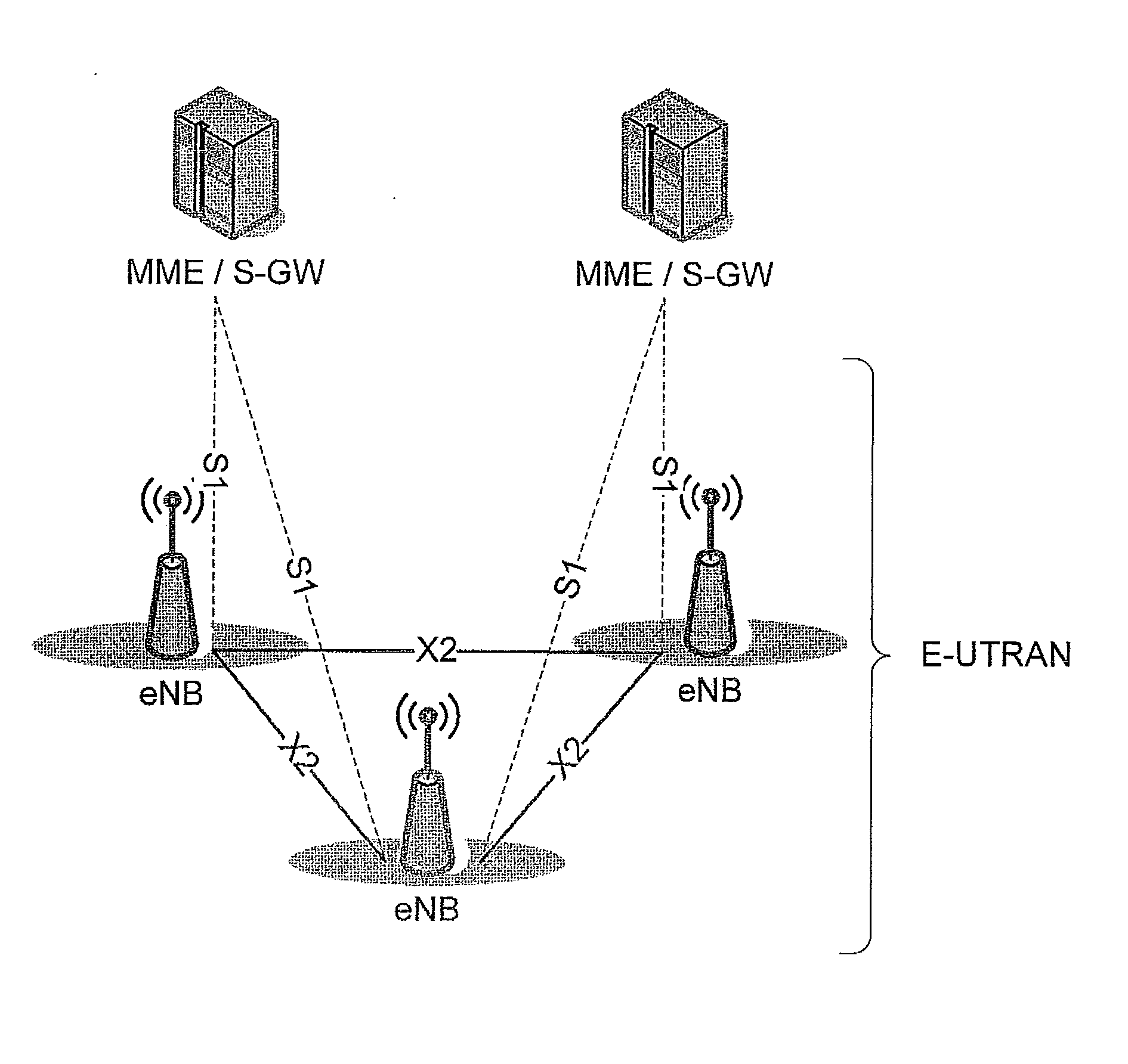
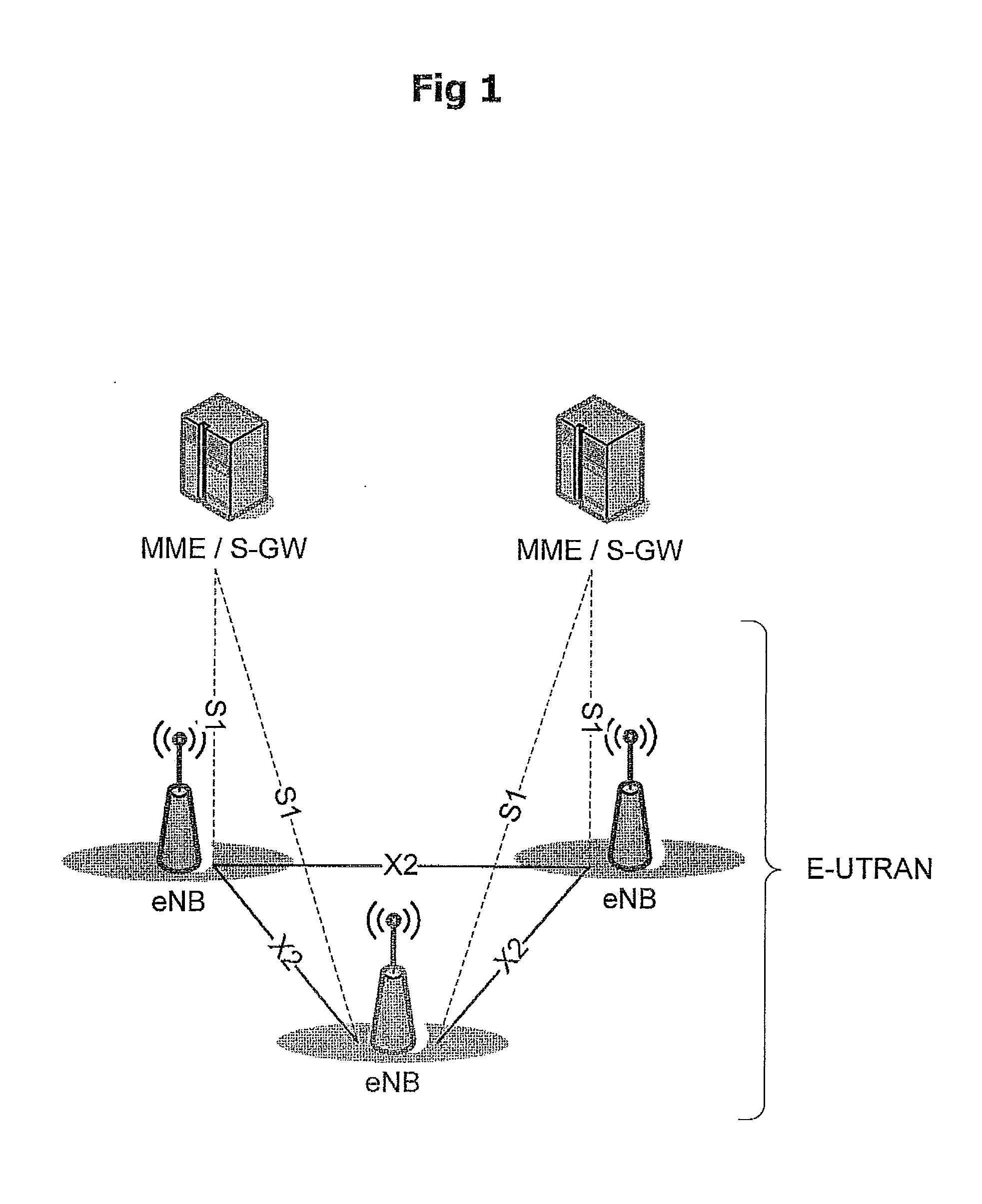
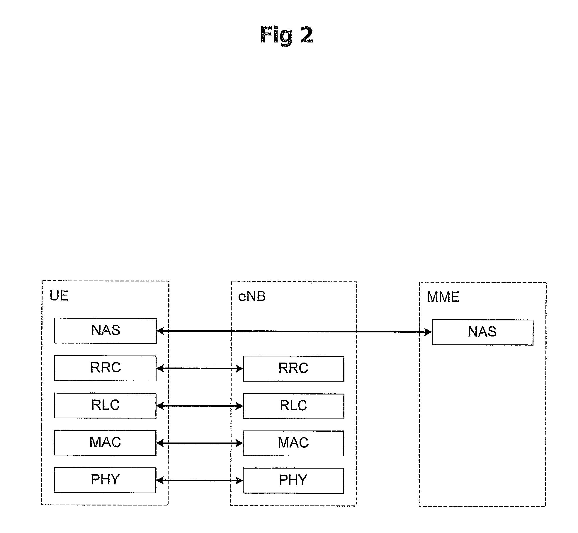
BACKGROUND OF THE INVENTION[0001]1. Field of the Invention[0002]The present invention relates to a method of receiving a disaster warning message (or any warning message) in wireless communication system. More particularly, a terminal (UE), which attempts to receive the warning message, receives a Broadcast Control Channel (BCCH) within a corresponding cell, obtains system information through the BCCH, and receives a warning message through a downlink channel according to scheduling information about the warning message included in the system information.[0003]2. Description of the Related Art[0004]FIG. 1 shows an exemplary network structure of an Evolved Universal Mobile Telecommunications System (E-UMTS) as a mobile communication system to which a related art and the present invention are applied. The E-UMTS system is a system that has evolved from the UMTS system, and its standardization work is currently being performed by the 3GPP standards organization. The E-UMTS system can a...

Claims


Application Information

Patent Timeline
Patent Type & Authority Applications(United States)
IPC IPC(8): H04M11/04H04W4/90
CPCH04W4/12H04W4/22H04W76/007H04W72/12H04W48/12H04W76/50H04W4/90Y02D30/70
Inventor LEE, YOUNG-DAEPARK, SUNG-JUNYI, SEUNG-JUNECHUN, SUNG-DUCK
Owner LG ELECTRONICS INC
Why Eureka
Try Eureka