Ignition system utilizing igniter and gas injector

a technology of igniter and gas injector, which is applied in the direction of engine starters, electric control, machines/engines, etc., can solve the problems of limited emission reduction from a typical engine operated in a lean mode, insufficient conventional igniters (spark plugs, glow plugs, etc.) to initiate and/or maintain combustion of mixtures, and difficult ignition of lean air/fuel mixtures, etc., to achieve the effect of facilitating auto-ignition of fuel mixtur

Inactive Publication Date: 2009-10-01
CATERPILLAR INC
View PDF22 Cites 29 Cited by
  • Summary
  • Abstract
  • Description
  • Claims
  • Application Information

AI Technical Summary

Benefits of technology

[0010]In another aspect, the present disclosure is directed to a method of initiating combustion within an engine. The method may include locally heating a fuel mixture within the engine to initiate combustion during a first mode of engine operation, and ceasing the local heating during a second mode of engine operation. The method may further include injecting a non-combustible gas into the engine during the second mode of engine operation to facilitate auto-ignition of the fuel mixture.

Problems solved by technology

Although successful at reducing emissions, very lean air / fuel mixtures are difficult to ignite.
That is, a conventional igniter (spark plug, glow plug, etc.) may be insufficient to initiate and / or maintain combustion of a mixture that has little fuel (compared to the amount of air present).
As a result, the emission reduction available from a typical engine operated in a lean mode may be limited.
In addition, conventional igniters suffer from low component life.
Specifically, in some situations such as during startup or cold operation, the injection of non-combustible gas may, alone, be insufficient to promote auto-ignition.

Method used


Image

  • Ignition system utilizing igniter and gas injector
  • Ignition system utilizing igniter and gas injector
  • Ignition system utilizing igniter and gas injector

Examples


Embodiment Construction

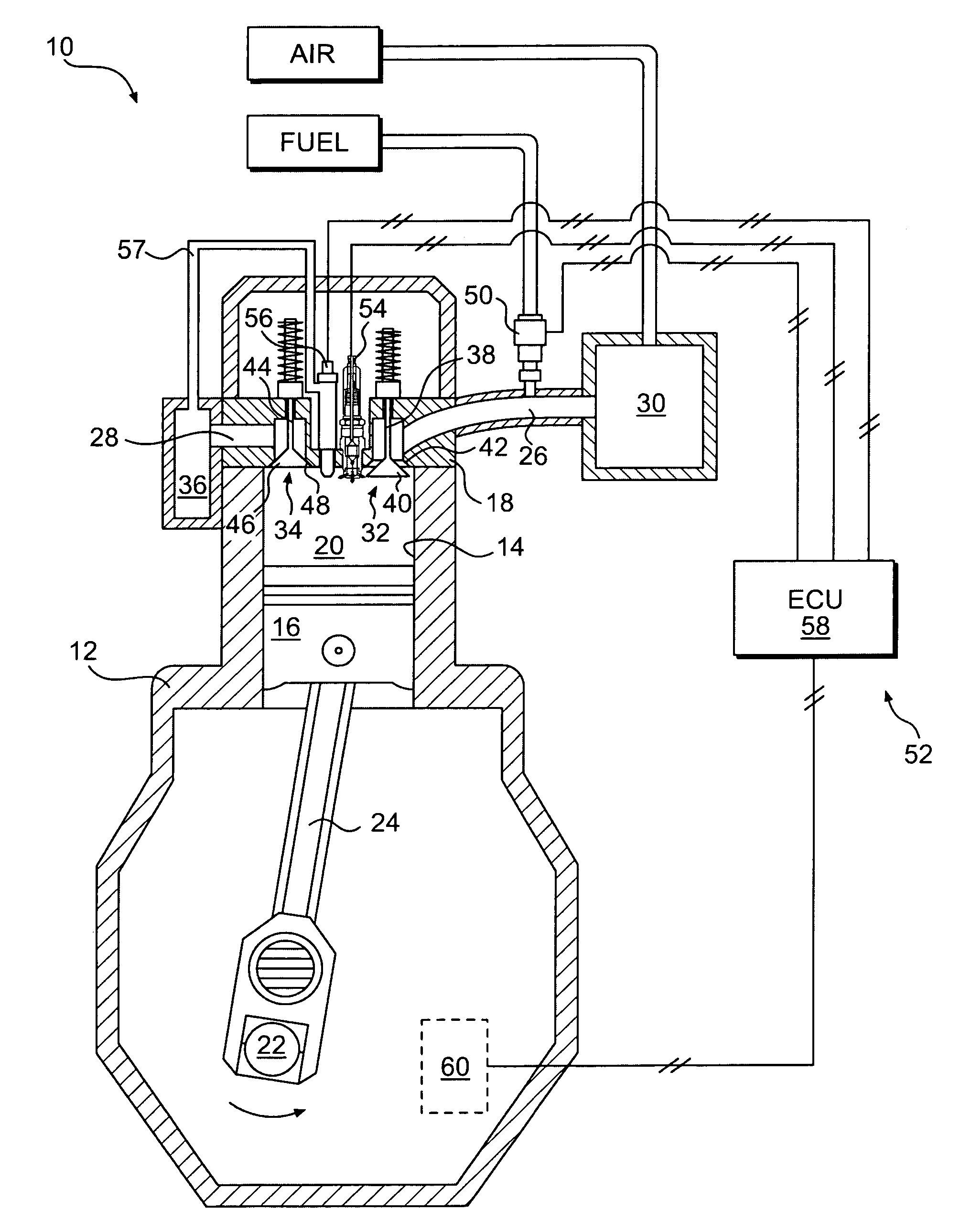
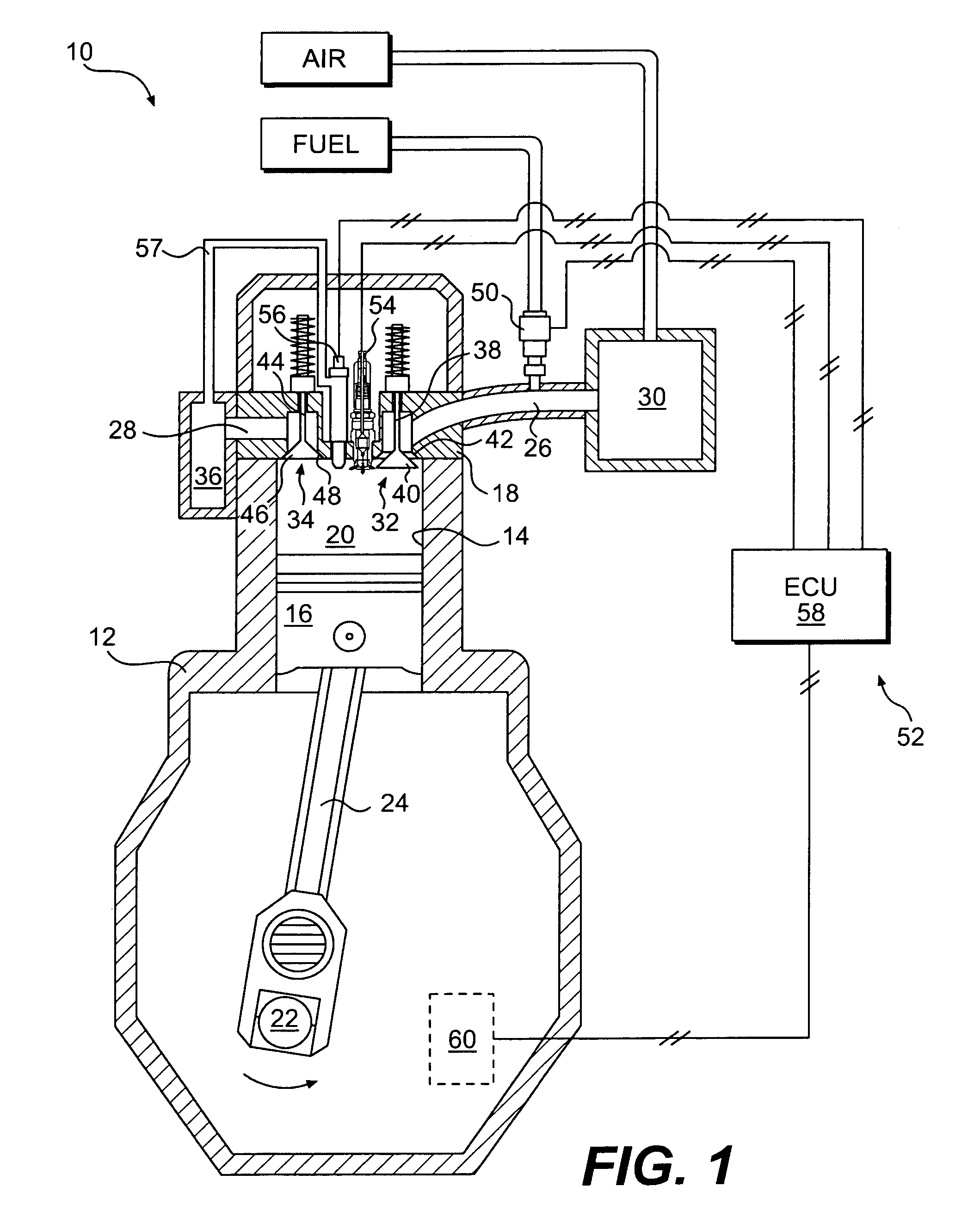
[0013]FIG. 1 illustrates an exemplary combustion engine 10. For the purposes of this disclosure, engine 10 is depicted and described as a four-stroke gaseous-fueled engine, for example a natural gas engine. One skilled in the art will recognize, however, that engine 10 may be any other type of combustion engine such as, for example, a gasoline or a diesel-fueled engine. Engine 10 may include an engine block 12 that at least partially defines one or more cylinders 14 (only one shown in FIGS. 1 and 2). A piston 16 may be slidably disposed within each cylinder 14 to reciprocate between a top-dead-center (TDC) position and a bottom-dead-center (BDC) position, and a cylinder head 18 may be associated with each cylinder 14. Cylinder 14, piston 16, and cylinder head 18 may together define a combustion chamber 20. It is contemplated that engine 10 may include any number of combustion chambers 20 and that combustion chambers 20 may be disposed in an “in-line” configuration, a “V” configurati...


PUM


Abstract

An ignition system for use with an engine is disclosed. The ignition system may have an igniter connected to selectively ignite a fuel mixture within the engine, an injector located to inject a non-combustible gas into the engine, and a controller in communication with the igniter and the injector. The controller may be configured to energize the igniter during a first mode of engine operation to ignite the fuel mixture, and cease energizing the igniter during a second mode of engine operation. The controller may also be configured to actuate the injector during the second mode of engine operation to promote auto-ignition of the fuel mixture.

Description

TECHNICAL FIELD[0001]The present disclosure relates generally to an ignition system and, more particularly, to an ignition system using an igniter and a gas injector to initiate combustion.BACKGROUND[0002]Engines, including diesel engines, gasoline engines, gaseous fuel powered engines, and other engines known in the art ignite an air / fuel mixture to produce heat. In one example, fuel injected into a combustion chamber of the engine is ignited by way of a spark plug, a glow plug, or an AC / DC ignition source. The heat and expanding gases resulting from this combustion process are directed to displace a piston or move a turbine blade, both of which can be connected to a crankshaft of the engine. As the piston is displaced or the turbine blade is moved, the crankshaft is caused to rotate. This rotation is utilized to directly drive a device such as a transmission to propel a vehicle, or a generator to produce electrical power.[0003]During operation of the engine described above, a comp...

Claims


Application Information

Patent Timeline
Patent Type & Authority Applications(United States)
IPC IPC(8): F02B5/02F02N17/04F02N17/08F02B19/12F02N19/00F02N19/04
CPCF02B7/06F02B19/14F02B47/08F02D41/3041Y02T10/125F02M25/0723F02M2023/008F02P19/02F02P23/04F02M25/00F02M26/20Y02T10/12
Inventor FIVELAND, SCOTT B.ANDERS, JONATHAN WILLIAM
Owner CATERPILLAR INC
Why Eureka
Try Eureka