Method for Electromagnetic Geophysical Surveying of Subsea Rock Formations

a geophysical surveying and electromagnetic technology, applied in the field of electromagnetic geophysical surveying of subsea rock formations, can solve the problem that the method of srnka does not provide a solution to the problem of airborne electromagnetic waves, and achieve the effect of reducing upward propagating energy and reducing undesired air waves

Active Publication Date: 2009-10-01
NORSK HYDRO ASA +1
View PDF8 Cites 13 Cited by
  • Summary
  • Abstract
  • Description
  • Claims
  • Application Information

AI Technical Summary

Benefits of technology

The present inventors have developed an improved method for transmitting signals over long distances without causing unwanted noise from other sources like ships' radar systems. This makes it easier to see through underwater oil wells with strong radioactive materials located deeper than water.

Problems solved by technology

The technical problem addressed in this patent text is the need to reduce the upward transmitted electromagnetic signal and produce a stronger electromagnetic signal to propagate downwards from the transmitter antenna and through the seafloor for propagating through the rock formations to be surveyed.

Method used


Image

  • Method for Electromagnetic Geophysical Surveying of Subsea Rock Formations
  • Method for Electromagnetic Geophysical Surveying of Subsea Rock Formations
  • Method for Electromagnetic Geophysical Surveying of Subsea Rock Formations

Examples


Embodiment Construction

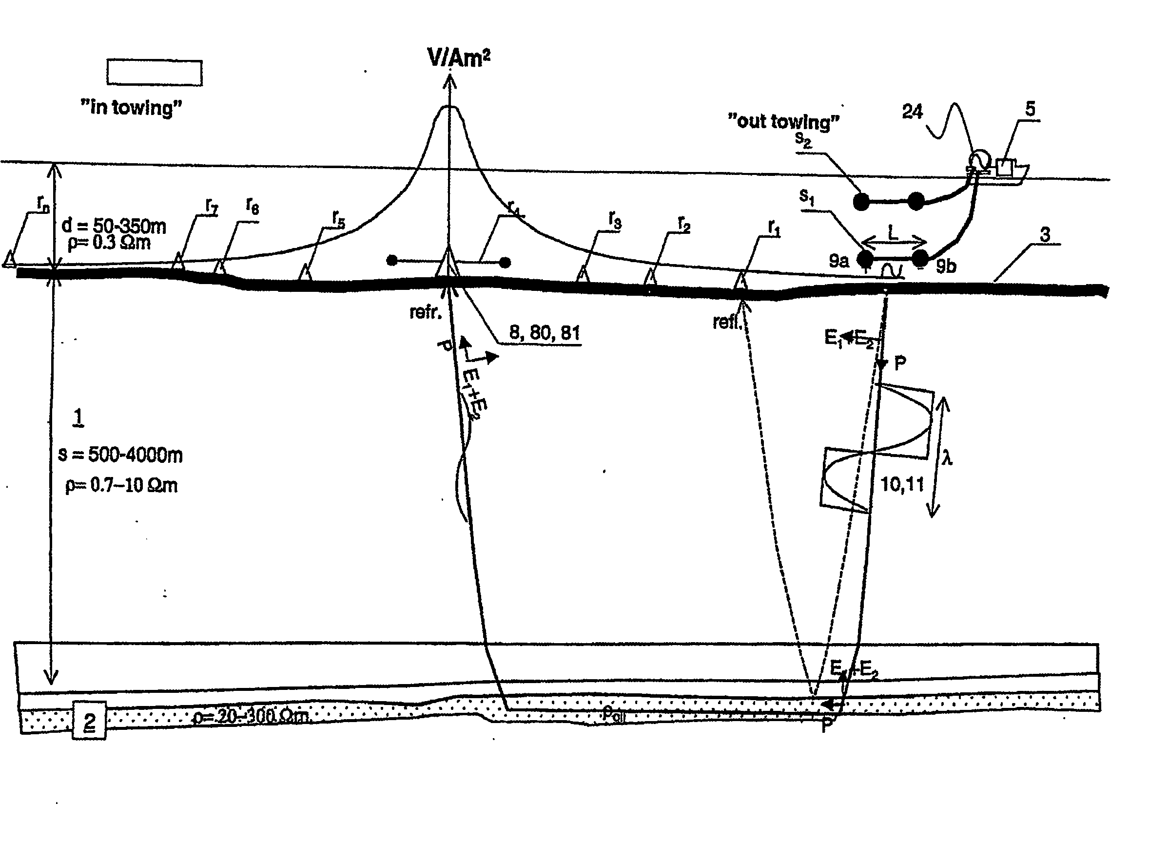
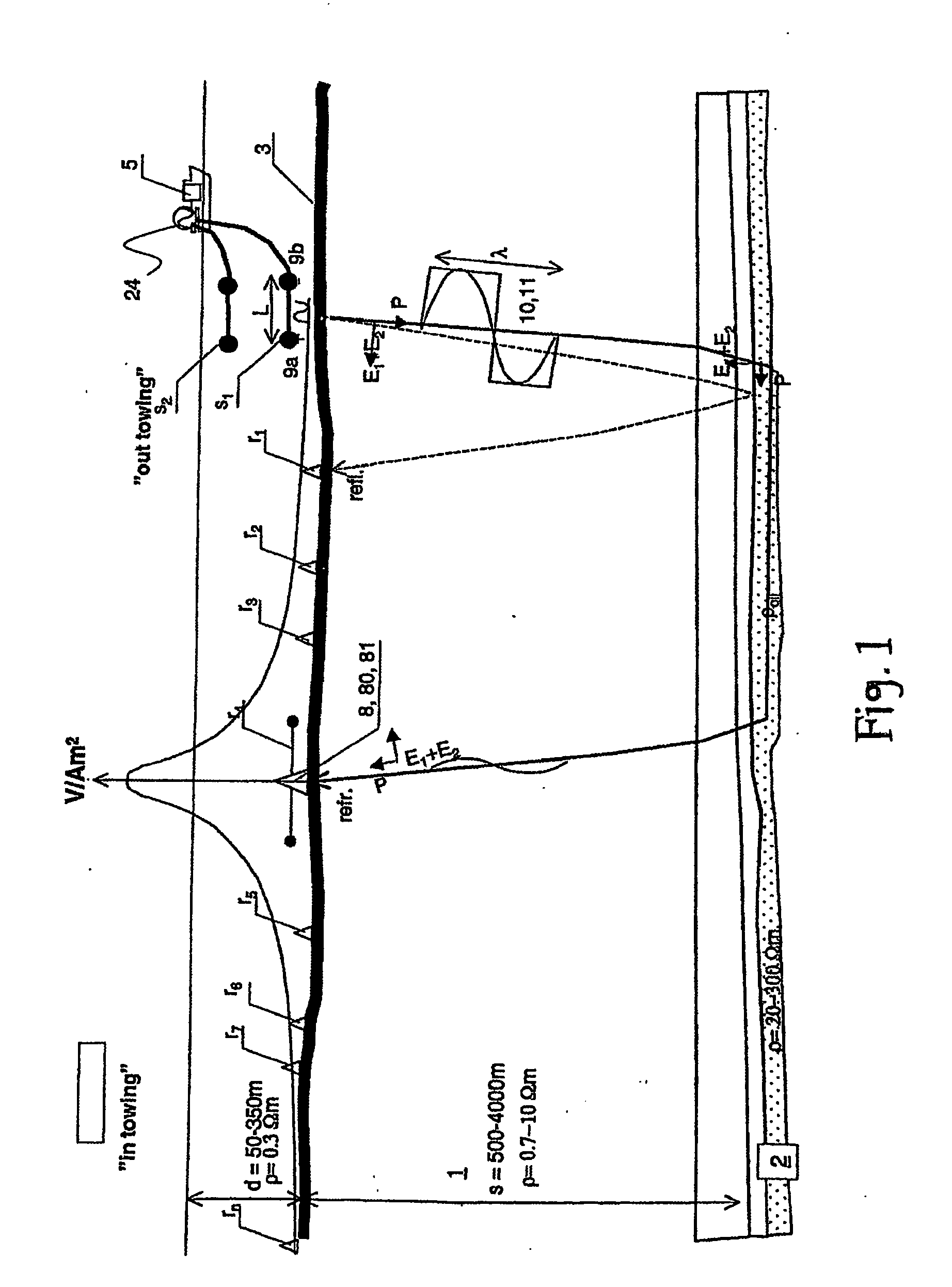
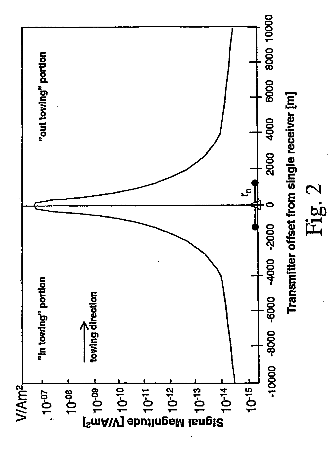
[0043]FIG. 1 illustrates a real-array alternative embodiment of the invention. The method comprises simultaneous towing of two horizontal electric dipoles s1 and s2 through the sea. The dipoles are vertically displaced relative to each other, and are operated at different phases φ1 and φ2, and amplitudes A1 and A2, respectively. Electromagnetic receivers r1, r2, . . . , rn such as electric dipole antennas or magnetic receivers are arranged along the seafloor 3 for measuring the electromagnetic field that has propagated, although strongly attenuated, through the sea and preferably through the rock formations 1, 2. A potential petroleum bearing formation 2, i.e. a porous sandstone formation, is indicated buried below a geological overburden 1, i.e. shales and water-bearing sandstone formations. Reflection and refraction paths are illustrated by broken and continuous lines, respectively. A source-normalized electric field intensity curve is also roughly indicated for one single station...


PUM


Abstract

A method for electromagnetic geophysical surveying of rock formations (1) under a sea-floor (3) comprising the following steps: * —towing first and second alternating field (E1, E2) emitting sources (s1, S2) in first and second depths below the sea surface, said first field (E1) having a first phase (Φ1); —said second alternating field (E2) given a second phase (Φ2) different from said first phase (Φ1), said sources (S1, S2) constituting a phased array emitter antenna with directivity for transmitting a major proportion of the combined electromagnetic energy downwards; —said first and second fields (E1, E2) for propagating partly down through the sea-floor (3) and being reflected and/or refracted through said rock formations (1) and partly propagating back through the seafloor (3); —said first and said second fields (E1, E2) for merging to a total field and being measured by electromagnetic receivers (r1, r2, . . . , rn) recording corresponding field registrations (Er1(t), Er2(t), Er3(t), . . . , Ern(t)).

Description


Claims


Application Information

Patent Timeline
Owner NORSK HYDRO ASA
Why Eureka
Try Eureka