
Universal software defined home gateway

a software and gateway technology, applied in the field of system and method of communicating information, can solve the problems of difficult communication between devices, low cost effectiveness of ami systems, and inability to meet the needs of users,

Active Publication Date: 2009-10-01
M & FC HLDG LLC
View PDF25 Cites 95 Cited by
  • Summary
  • Abstract
  • Description
  • Claims
  • Application Information

AI Technical Summary

Benefits of technology

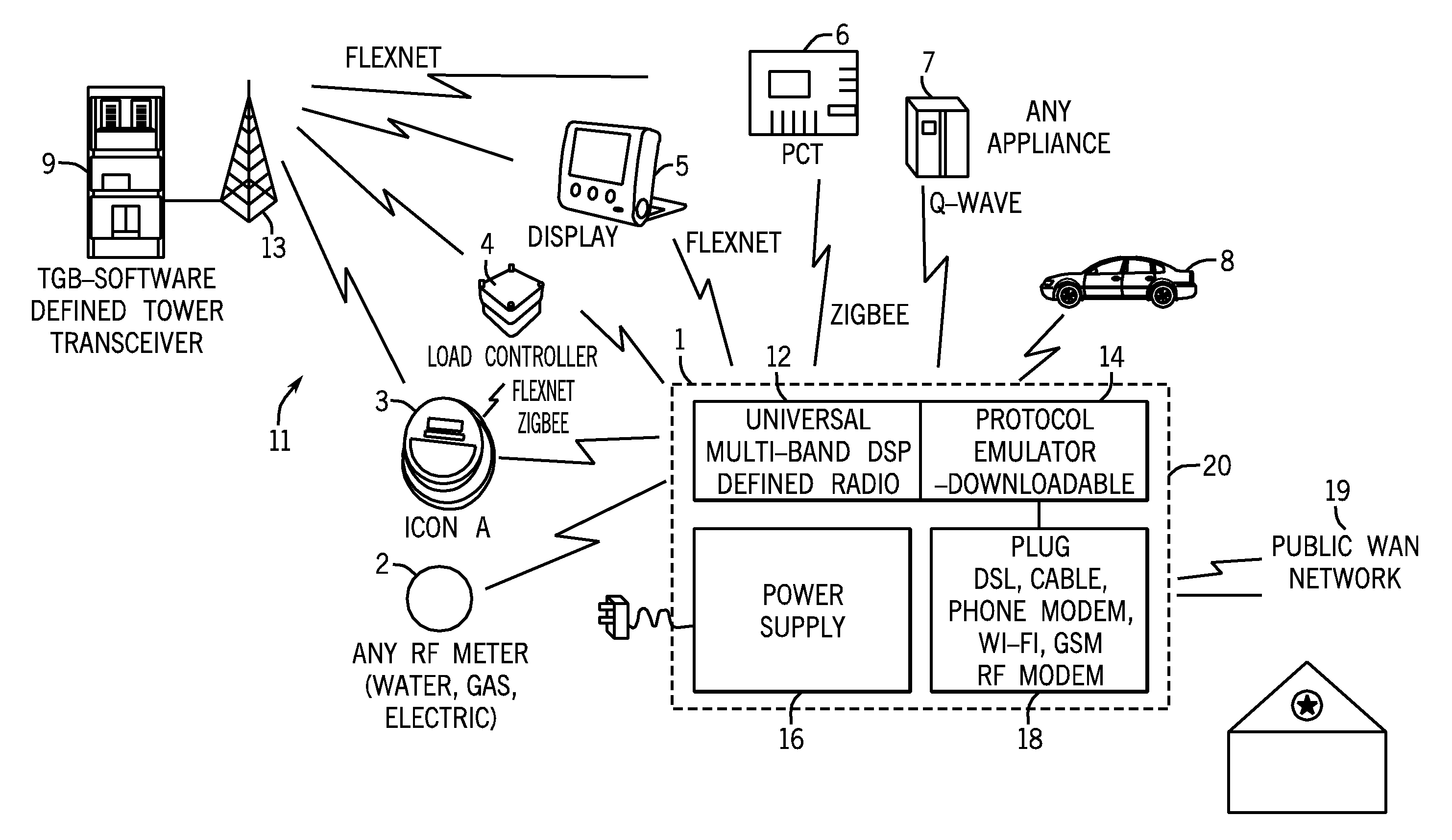
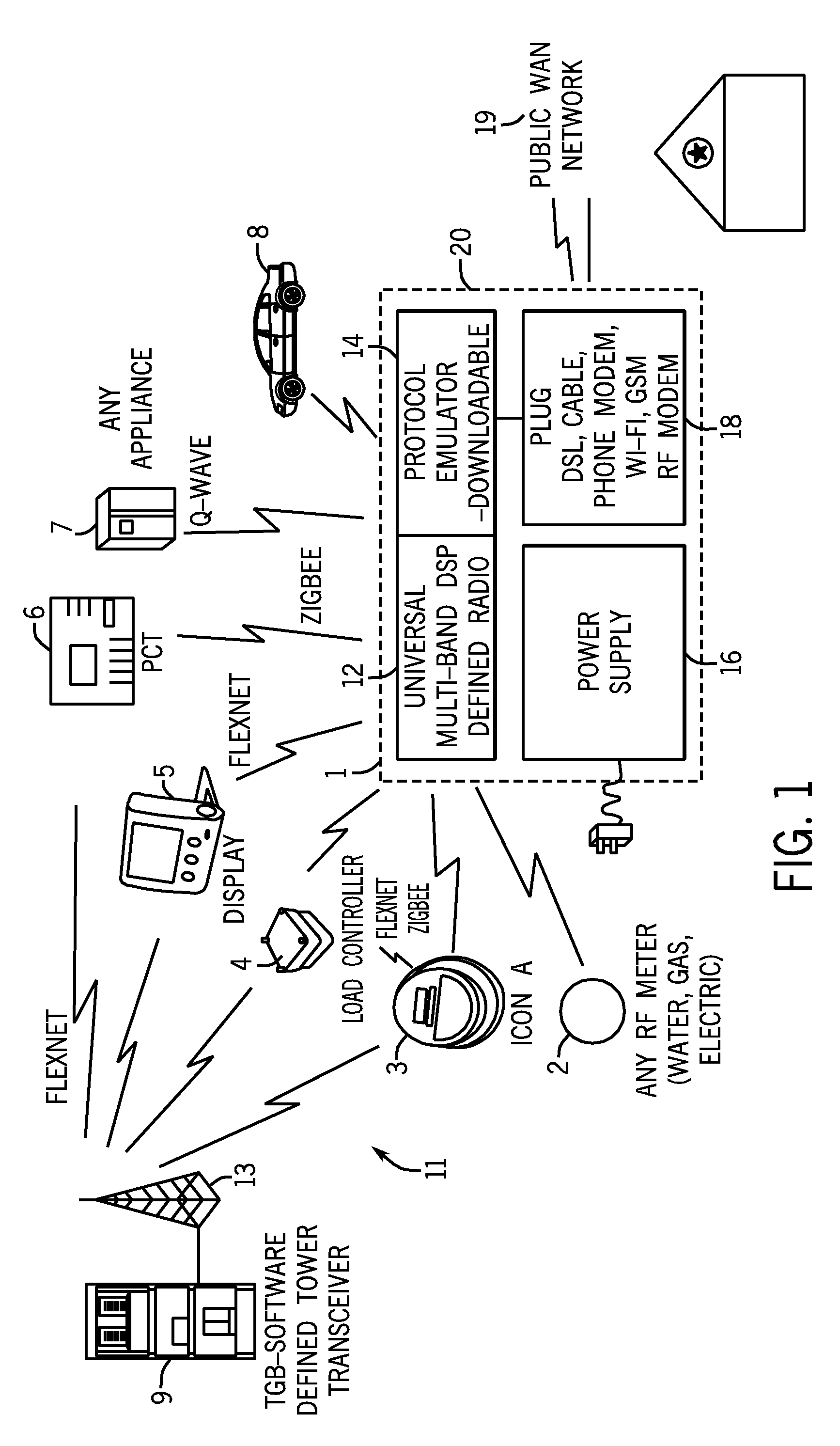
[0007]The home gateway contains a RF multi-band software defined radio. The radio is fully programmable and configurable so that it is capable of emulating, transmitting, and receiving any of a plurality of RF protocols. The radio is capable of multi-band operation so that it can simultaneously communicate with peripheral devices that operate on significantly different frequencies. The multi-band radio is capable of operating over multiple channels such that the radio can communicate over portions of different radio spectrums. The home gateway radio is capable of full-duplex operation, which enables it to simultaneously transmit and receive RF messages. The home gateway radio is also capable of half-duplex operation so that it either only transmits or receives RF messages at the same time.
[0008]The home gateway supports commonly used interfaces for communicating to the public WAN network, such as but not limited to DSL, Cable Modem, Phone Modem, USB,

Problems solved by technology

Although these types of AMI systems currently work effectively to receive utility consumption information from meters located within customer homes, the utility gateways must be mounted on towers or poles, which requires capital infrastructure expenditures by the utility.
In rural areas, AMI systems are often not cost effective due to the low density of the meters in such locations.
Thus, it is often difficult for devices to communicate with each other, or with a central location, utilizing the various different RF protocols available.

Method used


Image

  • Universal software defined home gateway
  • Universal software defined home gateway
  • Universal software defined home gateway

Examples


first embodiment

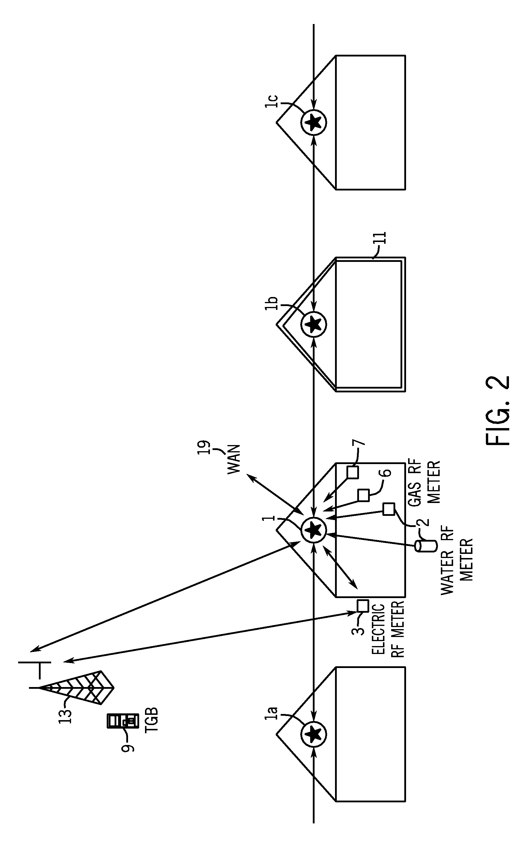
[0078]FIGS. 5a-5c are schematic illustrations of three different phases of the possible development of the software based home gateway of the present disclosure. In the first embodiment shown by FIG. 5a, the electricity meter 3 is shown including the home gateway 1. The electricity meter 3 communicates to the utility gateway 9 using the AMI system 11. Further, the home gateway 1 communicates using a wide area network 90. In this manner, the software within the home gateway can be updated for communication to various other devices located in an area near the home gateway 1.

[0079]In the embodiment shown in FIG. 5b, the home gateway 1 is shown as a separate device that communications with the various devices using various different communication protocols. Further, the home gateway is connected to the WAN 90 to receive software upgrades as is desired. In this embodiment, the home gateway 1 is a separate device having its own power supply connection 92. In the embodiment illustrated, th...

third embodiment

[0080]In the third embodiment shown in FIG. 5c, the home gateway 1 can receive a separate card 102 that provides the required communication such that the home gateway 1 can function as desired.


PUM


Abstract

A system and method for communicating energy or water consumption related information from a plurality of RF enabled peripheral devices in a home, such as utility meters, thermostats, appliances and load controllers. The system includes a home gateway that enables wireless RF peripheral devices in a home to communicate to a WAN network, such as the internet. The home gateway contains a RF multi-band software defined radio that is fully programmable and configurable so that it is capable of emulating, transmitting, and receiving any of a plurality of RF protocols over multiple RF channels. The home gateway supports commonly used interfaces for communicating to the public WAN network. The system also supports future peripherals that do not exist today due to the flexibility of the home gateway.

Description

CROSS-REFERENCE TO RELATED APPLICATION[0001]The present application is based on and claims priority to U.S. Provisional Patent Application Ser. No. 61 / 041,333, filed on Apr. 1, 2008.BACKGROUND OF THE INVENTION[0002]The present disclosure generally relates to a system and method for communicating information from a plurality of devices in a home to a remote location. More specifically, the present disclosure relates to a method and system that can communicate utility-related information from a home to a remote site, such as a utility, through either a home gateway located within a home or a utility gateway positioned remotely from the home.[0003]Presently, various different systems exist for a utility to receive consumption information from a plurality of meters distributed throughout a remote area. Many of these systems incorporate a gateway positioned within a neighborhood or a defined area that communicates using an RF local area network (LAN) to a plurality of meters distributed ...

Claims


Application Information

Patent Timeline
IPC IPC(8): G08B21/00H04W84/02
CPCG01D4/002Y02B90/246Y04S20/32Y02B90/241Y04S20/42Y02B90/20Y04S20/30G01D2204/45
Inventor SANDERFORD, JR., H. BRITTON
Owner M & FC HLDG LLC
Learn More