

Pit remover
a technology of removing blades and slits, which is applied in the field of removing blades, can solve the problems of inability to adapt the size of the central hub blades and undesirable six blades
- Summary
- Abstract
- Description
- Claims
- Application Information
AI Technical Summary
Benefits of technology
Problems solved by technology
Method used
Image

Examples
Embodiment Construction
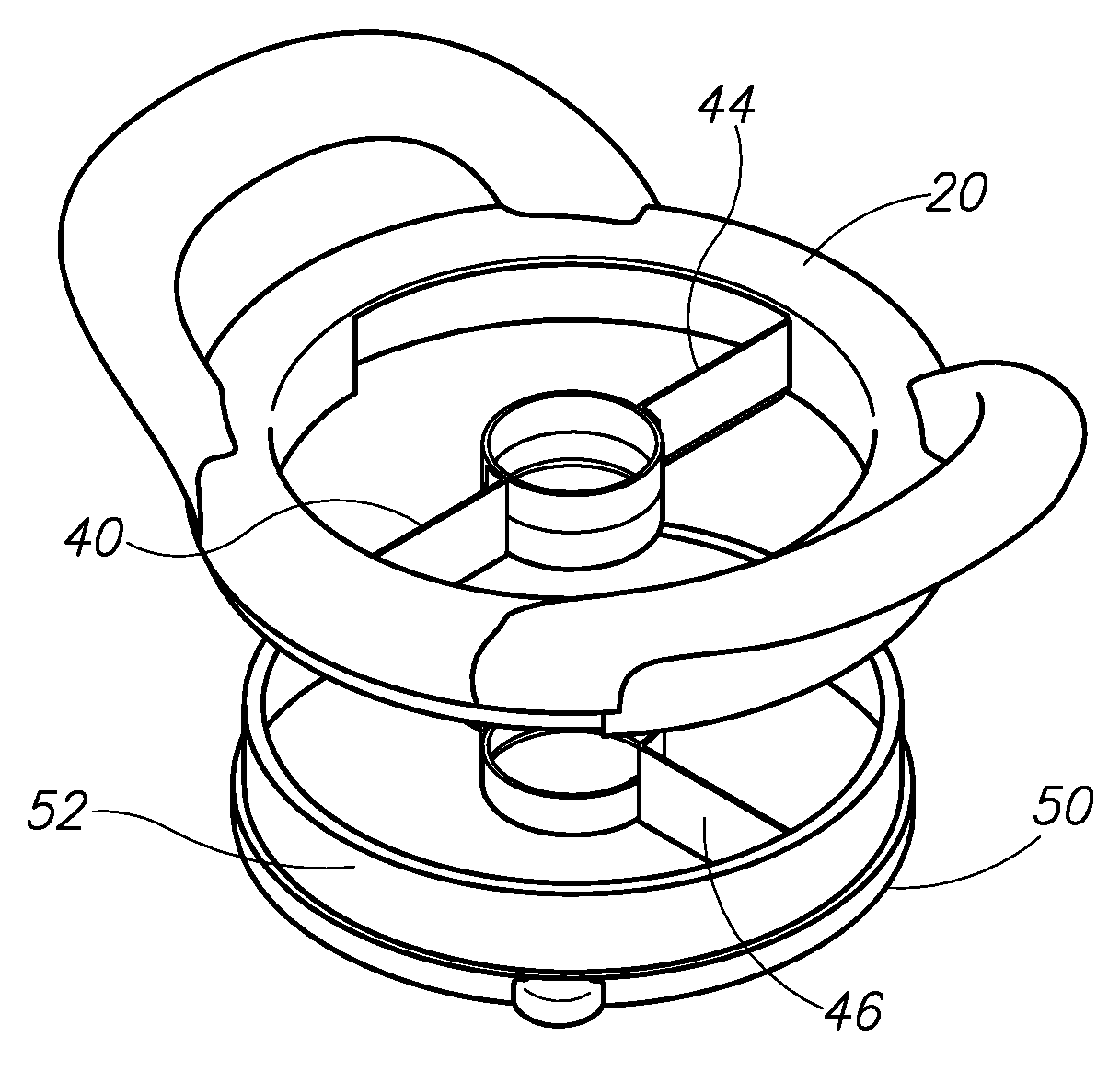
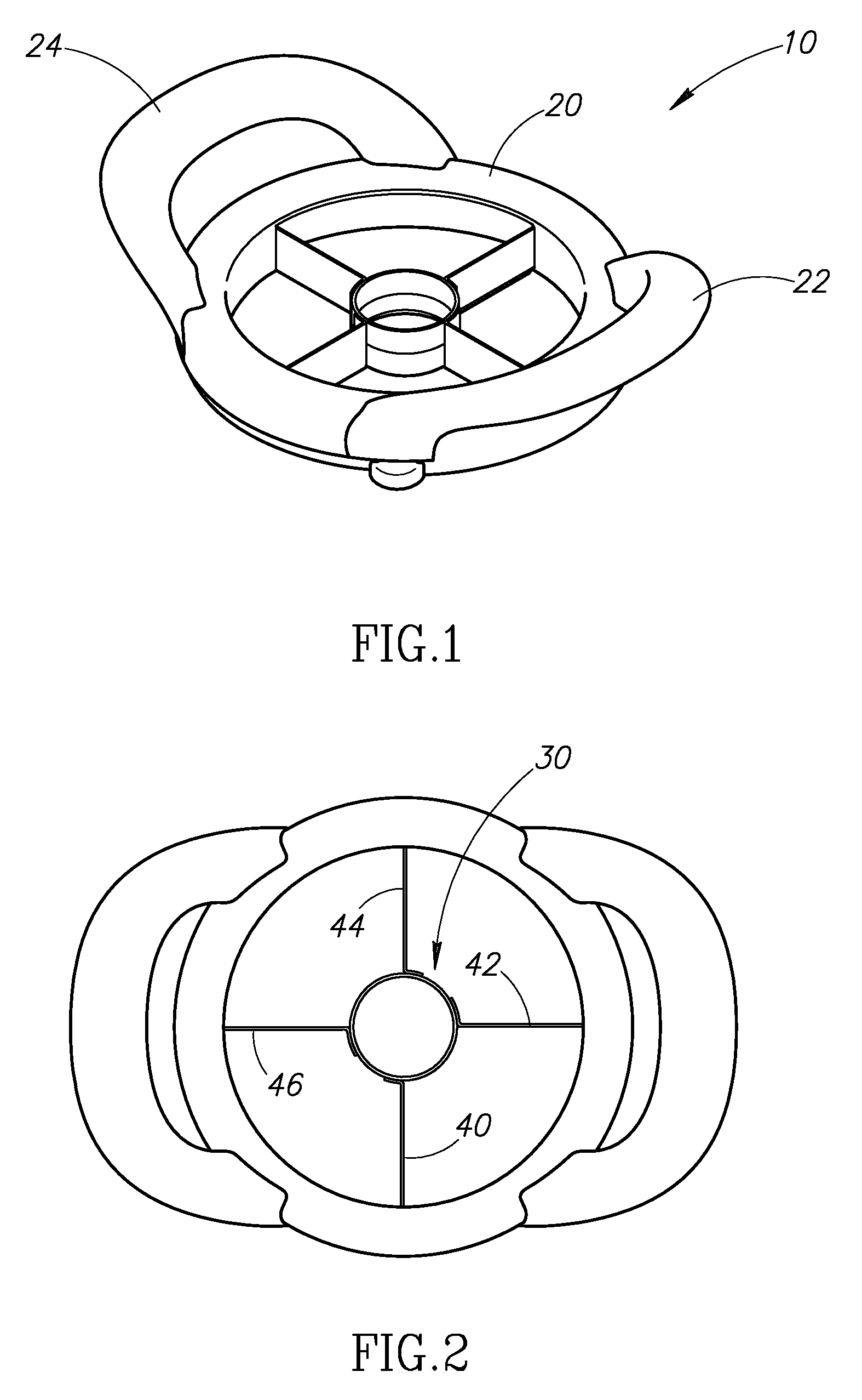
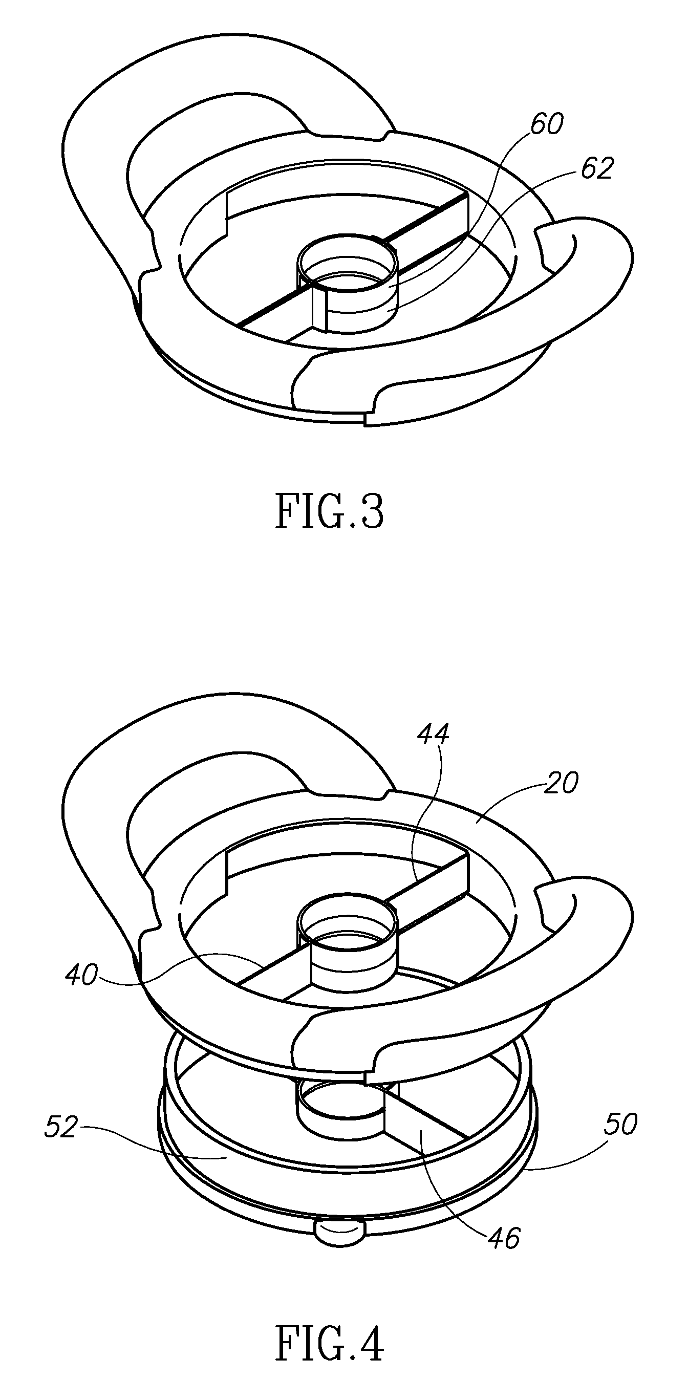
[0013]A preferred pit remover and slicer 10 is shown in FIGS. 1-6. In FIG. 1, a fully assembled device is shown in perspective view. As configured in FIG. 1, the pit remover and slicer includes an annular frame 20 having a pair of handles 22, 24. Each of the handles is provided on opposing sides of the frame, and each extends upward and radially outward from the frame. Though configured in the illustrated embodiment as having an annular frame, in other versions of the invention the frame may be square, rectangular, or have other shapes other than annular. Likewise, the handles need not extend upward and radially outward from the frame, but rather may be generally planar with the frame or may take the form of a peripheral flange extending uniformly about the circumference of the frame. For that matter, in some versions the handles may be omitted altogether.
[0014]Within the frame the device includes a circular central hub blade 30 and four substantially straight slicing blades 40, 42,...
PUM
 Abstract
Description
Claims
Application Information