Oscillating and gyrating stir stick for an ice container

a technology of ice container and stir stick, which is applied in the field of refrigerators, can solve the problems of forming ice clumps, multiple cubes freezing together, and difficult to ensure that all cubes are at a temperature to prevent melting, and achieve the effect of preventing the formation of ice clumps

Inactive Publication Date: 2014-02-06
WHIRLPOOL CORP
View PDF12 Cites 4 Cited by
  • Summary
  • Abstract
  • Description
  • Claims
  • Application Information

AI Technical Summary

Benefits of technology

[0008]It is another object, feature, and / or advantage of the present invention to provide an apparatus and method of preventing the formation of ice clumps in an ice container.
[0009]It is yet another object, feature, and / or advantage of the present invention to provide an apparatus and method for breaking up ice clumps that have formed in an ice container.
[0010]It is still another object, feature, and / or advantage of the present invention to provide an apparatus that includes a stir stick that oscillates while rotating in an ice container.
[0011]It is a further object, feature, and / or advantage of the present invention to provide an apparatus that provides a stir stick that is able to extend into the full area of an ice container.
[0012]It is still a further object, feature, and / or advantage of the present invention to provide an ice making system including a stir stick that includes bends and that is connected to a cam to oscillate and rotate.
[0013]It is another object, feature, and / or advantage of the present invention to provide an apparatus that allows for different configurations of ice containers to be used.

Problems solved by technology

However, as the amount of cubes accumulate in the ice container, it becomes more difficult to ensure that all of the cubes are at a temperature to prevent melting.
The melting and refreezing of the cubes can cause multiple cubes to freeze together, forming ice clumps.
However, the size and shape of ice containers do not make it feasible for the stir sticks to reach the full area within the containers.

Method used


Image

  • Oscillating and gyrating stir stick for an ice container
  • Oscillating and gyrating stir stick for an ice container
  • Oscillating and gyrating stir stick for an ice container

Examples


Embodiment Construction

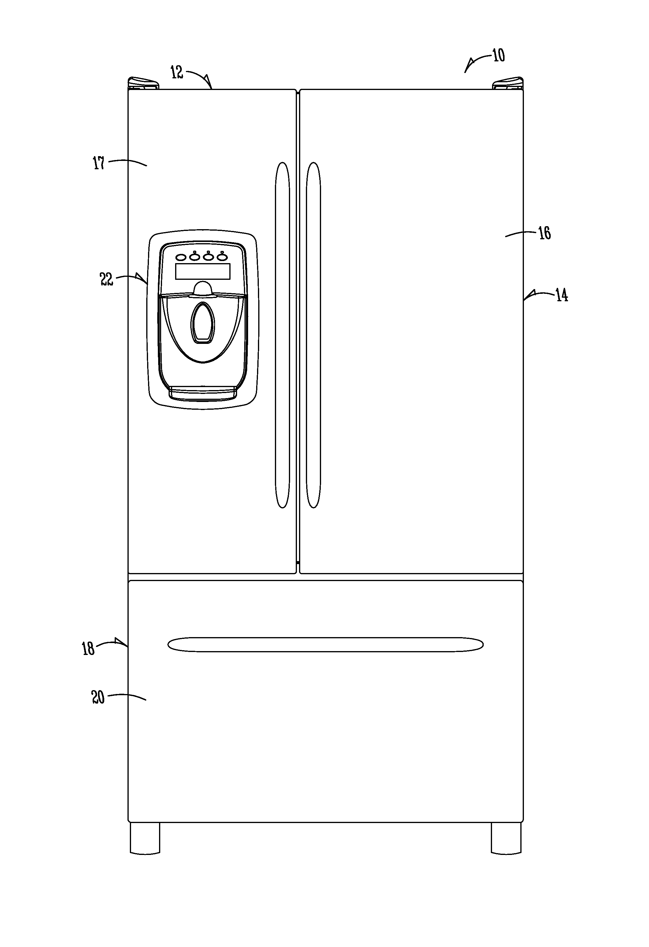
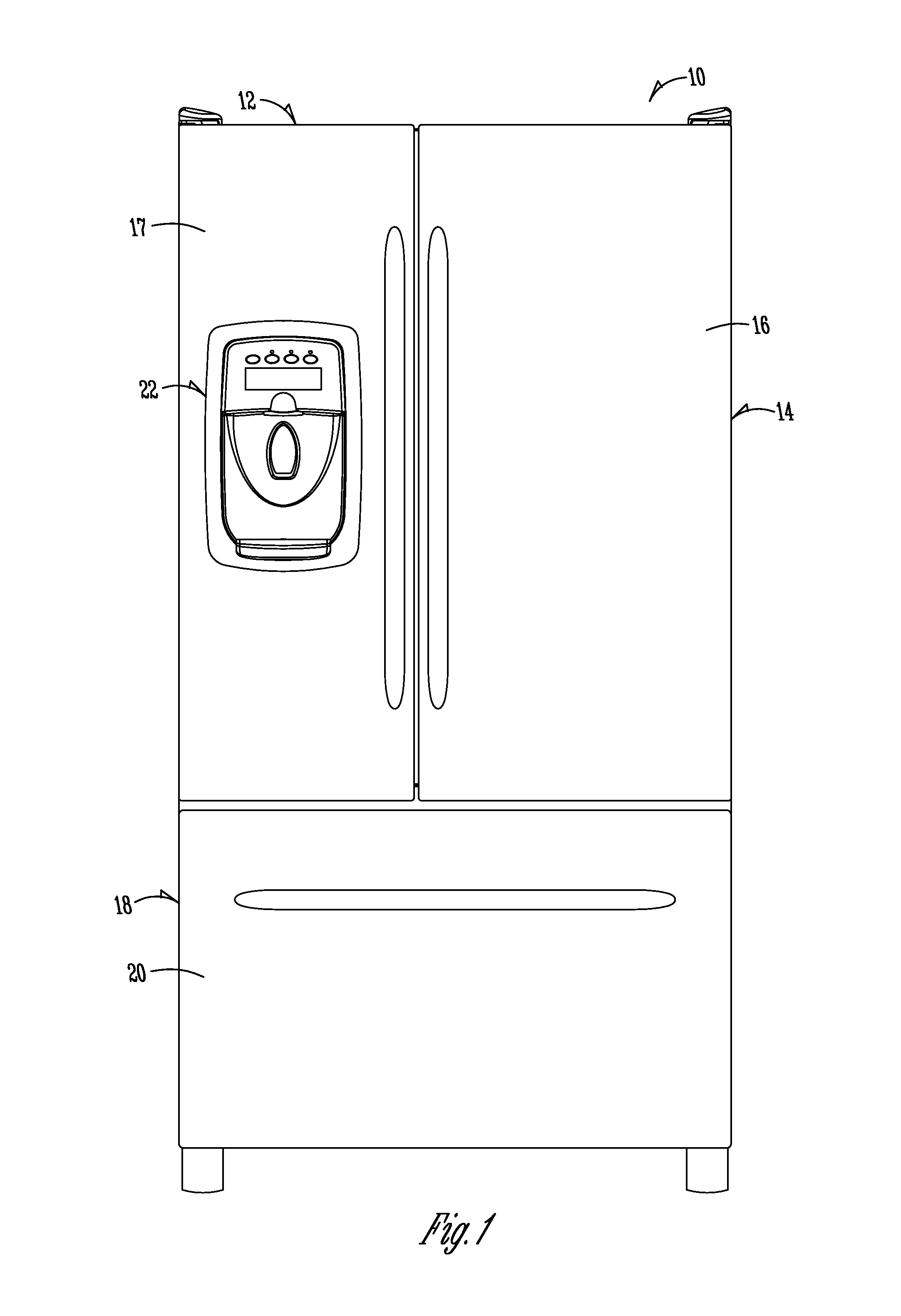
[0023]FIG. 1 is a front elevation view of a bottom mount refrigerator 10. The bottom mount refrigerator 10 includes a cabinet 12 encapsulating the compartments of the refrigerator 10. As shown in FIG. 1, the upper compartment is a refrigerator or fresh food compartment 14. First and second doors 16, 17 provide access to the interior of the refrigerator compartment 16. A dispenser 22 is positioned on one of the doors 17 of the refrigerator compartment 16. The dispenser 22 may be a water dispenser, ice dispenser, other beverage dispenser, or some combination thereof. Furthermore, the dispenser 22 may be placed on any door 16, 17, 20 of the refrigerator 10, or the dispenser 22 may be placed within one of the compartments of the refrigerator 10. For example, the dispenser 22 may be placed at one of the interior walls of the refrigerator compartment 16, thus being part of the cabinet 12. The placement of the dispenser 22 is not to limit the present invention. Positioned generally below t...


PUM


Abstract

A refrigerator is provided that includes an ice making system, that generally includes an ice maker for making ice, and an ice container for holding the formed ice. The ice making system may be positioned anywhere within the refrigerator, and it may be a modular ice system. The shape of the ice container limits the amount of useable space taken up by the system. The ice container includes a stir stick positioned within the ice container. The stir stick is configured to rotate and oscillate in a direction generally perpendicular to the axis of rotation of the stir stick to provide movement of the stir stick into the full area of the ice container. The rotation and oscillation of the stir stick prevents ice from melting and clumping in the corners of the ice container, while also aiding in directing the ice towards a dispensing aperture of the ice container.

Description

FIELD OF THE INVENTION[0001]The present invention relates generally to the field of refrigerators. More particularly, but not exclusively, the invention relates to an apparatus for preventing ice clumps and breaking up formed ice clumps in an ice container.BACKGROUND OF THE INVENTION[0002]Ice makers may be included with refrigerators, or may be stand-alone units. In general, the ice maker includes a water source, a cooling source, a mold, and an ejecting mechanism. Water is added to the mold, and the cooling source removes heat from the water to lower the temperature below freezing, at which time ice cubes are formed. Once the cubes have formed, the ejecting mechanism operates to remove or eject the formed cubes from the molds, at which point new water can be added and the process repeated.[0003]The ejected ice cubes are generally directed towards an ice container or ice storage bin. In refrigerators and in stand-alone units, the ice container is located generally adjacent the ice m...

Claims


Application Information

Patent Timeline
Patent Type & Authority Applications(United States)
IPC IPC(8): F25C5/16F25C5/18
CPCF25C5/182F25C5/22F25C5/04F25C2500/08
Inventor VISIN, JEROLD M.
Owner WHIRLPOOL CORP
Why Eureka
Try Eureka