Seal for unloading conveyor arrangement

a conveyor and belt technology, applied in the field of belt conveyors, can solve the problems of not providing a closure capability to prevent entry, not typically adjustable boots, and only minimal grain flow control and guidan

Active Publication Date: 2016-10-18
BLUE LEAF I P INC
View PDF26 Cites 4 Cited by
  • Summary
  • Abstract
  • Description
  • Claims
  • Application Information

AI Technical Summary

Benefits of technology

[0014]An advantage of the present disclosure is that the seal prevents material which is discharged from the conveyor from flowing through the gap between the conveyor and the spout.
[0020]Yet a further advantage is that the conveyor arrangement can be differently configured, such as an auger, a belt conveyor or a chain elevator.

Problems solved by technology

However, such boots are not typically adjustable, and provide only minimal grain flow control and guidance, and little or no extension of the effective length of the conveyor.
Such boots also do not provide a closure capability to prevent entry of contaminants, nor an ability to prevent dribbling of grain after an unloading operation.
This can be relatively easy to accomplish if the combine and receiving container are stationary, but becomes more difficult if the harvester and the receiving container are moving, and the difficulty increases further if the terrain is uneven and / or sloped, and / or a strong, gusting, and / or direction changing wind is present.
Further, the grain holding capacity of many harvesters and receiving containers is quite large, and it may be necessary to vary the grain flow location to spread the grain within the receiving container to prevent spillage over the side of the receiving container.

Method used


Image

  • Seal for unloading conveyor arrangement
  • Seal for unloading conveyor arrangement
  • Seal for unloading conveyor arrangement

Examples


Embodiment Construction

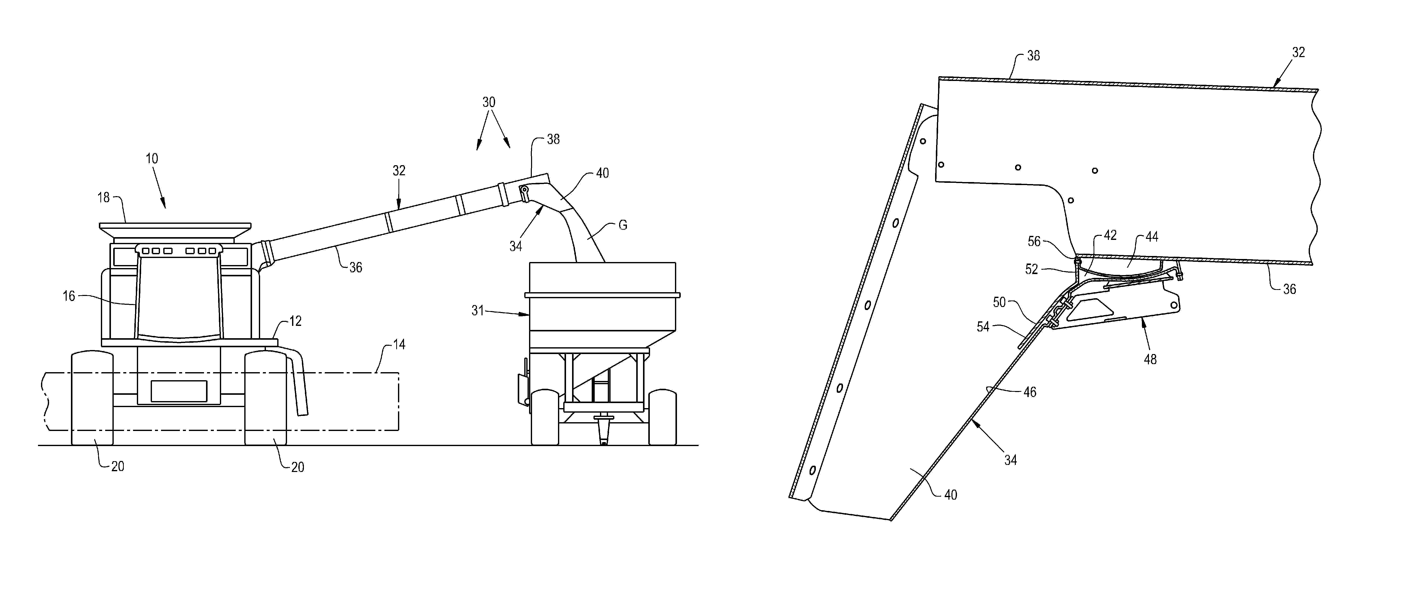
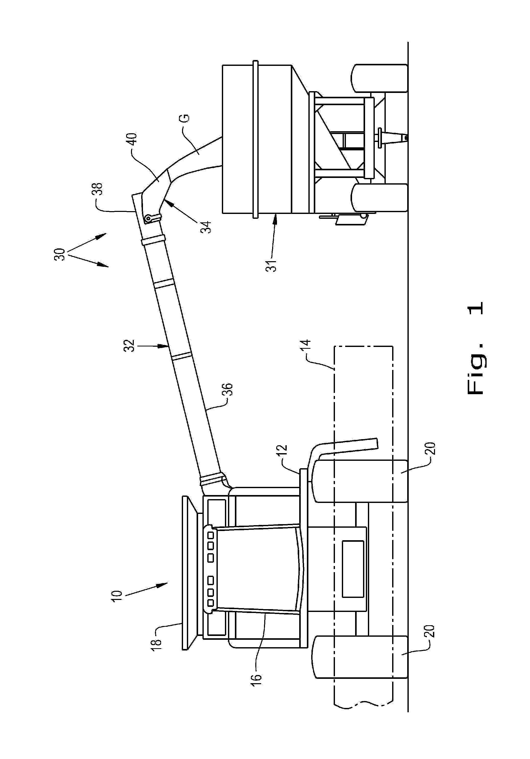
[0031]Referring now to the drawings, and more particularly to FIG. 1, there is shown a portion of an agricultural machine in the form of a combine harvester 10. Combine 10 generally includes a chassis 12 which carries a number of other components such as a header 14, operator station 16, clean grain tank 18, etc. Motive force can typically be applied through a number of ground engaging wheels, including front drive wheels 20. It may also be possible to use driven tracks (half or full) for some applications.

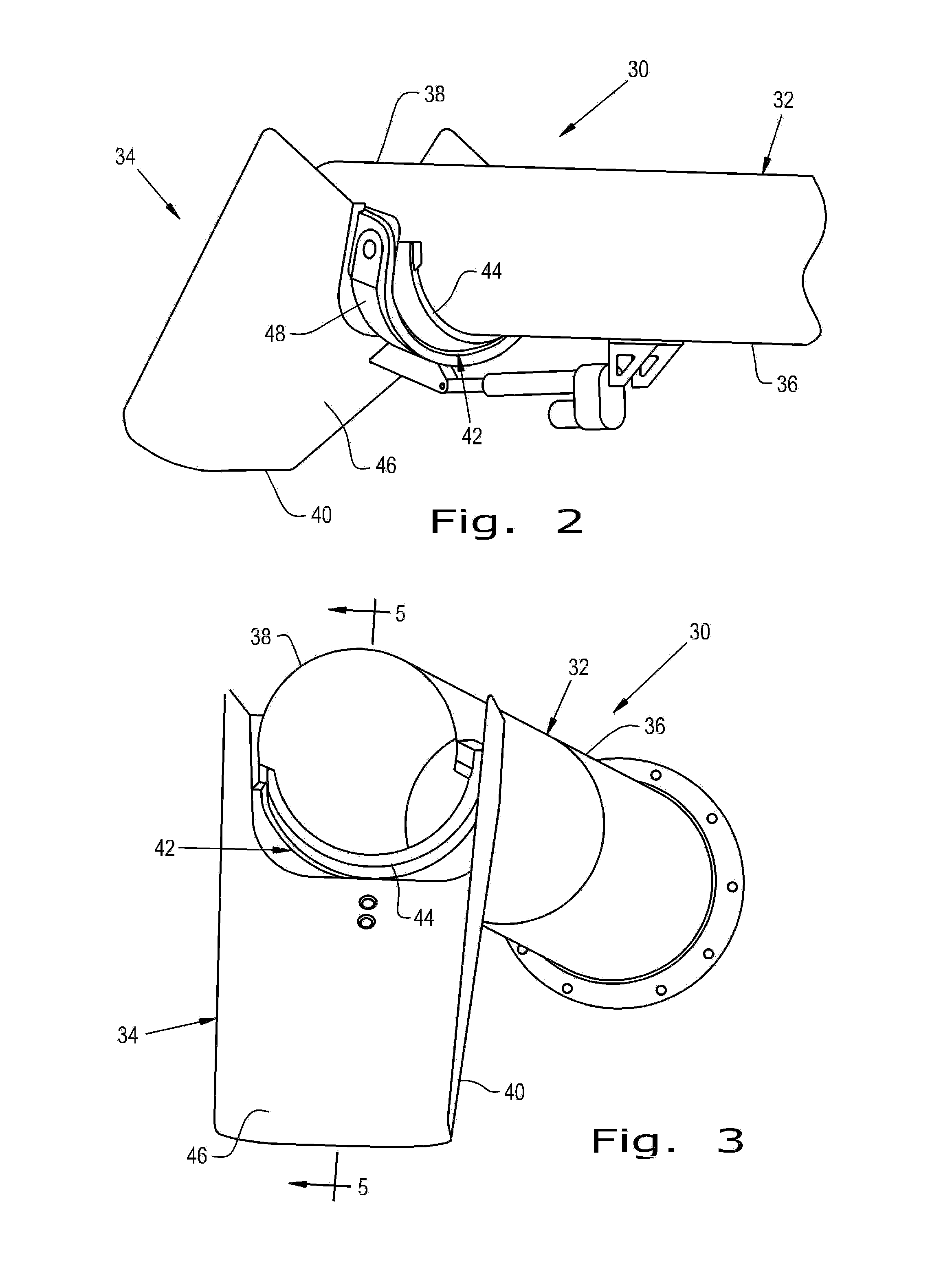
[0032]According to an aspect of the present disclosure, combine 10 also includes an unloading conveyor arrangement 30 which is operable to unload grain “G” (or other material) into a receiving container, such as a gravity wagon 31. Unloading conveyor arrangement 30 generally includes a conveyor 32 and spout arrangement 34. As shown in FIGS. 2 and 3, conveyor 32 can be in the form of an auger with a helical flighting (not shown) which is rotatably positioned within an auger tube 36...


PUM


Abstract

An unloading conveyor arrangement for an agricultural machine includes a conveyor having a discharge end, and a spout arrangement at the discharge end of the conveyor. The spout arrangement includes a spout which is connected to the discharge end and movable relative to the conveyor. The spout and the discharge end have an interspatial gap therebetween. The spout arrangement further includes a seal which is attached to the conveyor and / or the spout and extends across the interspatial gap.

Description

CROSS REFERENCE TO RELATED APPLICATIONS[0001]This is a non-provisional patent application based upon U.S. provisional patent application Ser. No. 61 / 795,573, entitled “PIVOTING UNLOAD SPOUT—GRAIN SEAL WITH NON-LINEAR HINGE”, filed Oct. 19, 2012, which is incorporated herein by reference.BACKGROUND OF THE INVENTION[0002]1. Field of the Invention[0003]The present disclosure relates to unloading conveyors for agricultural harvesters, and, more particularly, to spout arrangements at the discharge end of such unloading conveyors.[0004]2. Description of the Related Art[0005]Unloading of grain from agricultural machines such as combine harvesters is typically accomplished using an elongate unloading conveyor. Such unloading conveyors typically are helical auger type conveyors. The conveyors have a discharge end including a discharge opening through which the grain is propelled by the operation of the conveyor. On some conveyors, the discharge opening faces longitudinally or endwardly such ...

Claims


Application Information

Patent Timeline
Patent Type & Authority Patents(United States)
IPC IPC(8): A01D17/02A01F12/46F16J15/02A01D41/12
CPCA01D41/1217F16J15/02
Inventor COPPINGER, JASON R.SCHEURING, BRIAN L.FARLEY, HERBERT M.LINDE, COOPER W.
Owner BLUE LEAF I P INC
Why Eureka
Try Eureka