Printed circuit board

Active Publication Date: 2009-10-08
NITTO DENKO CORP
View PDF7 Cites 5 Cited by
  • Summary
  • Abstract
  • Description
  • Claims
  • Application Information

AI Technical Summary

Benefits of technology

[0018]An object of the present invention is to provide a printed circuit

Problems solved by technology

This may cause a transmission error of a differential signal through the write conductors W1,

Method used


Image

  • Printed circuit board
  • Printed circuit board
  • Printed circuit board

Examples


first embodiment

[0045](1) Configuration of the Suspension Board

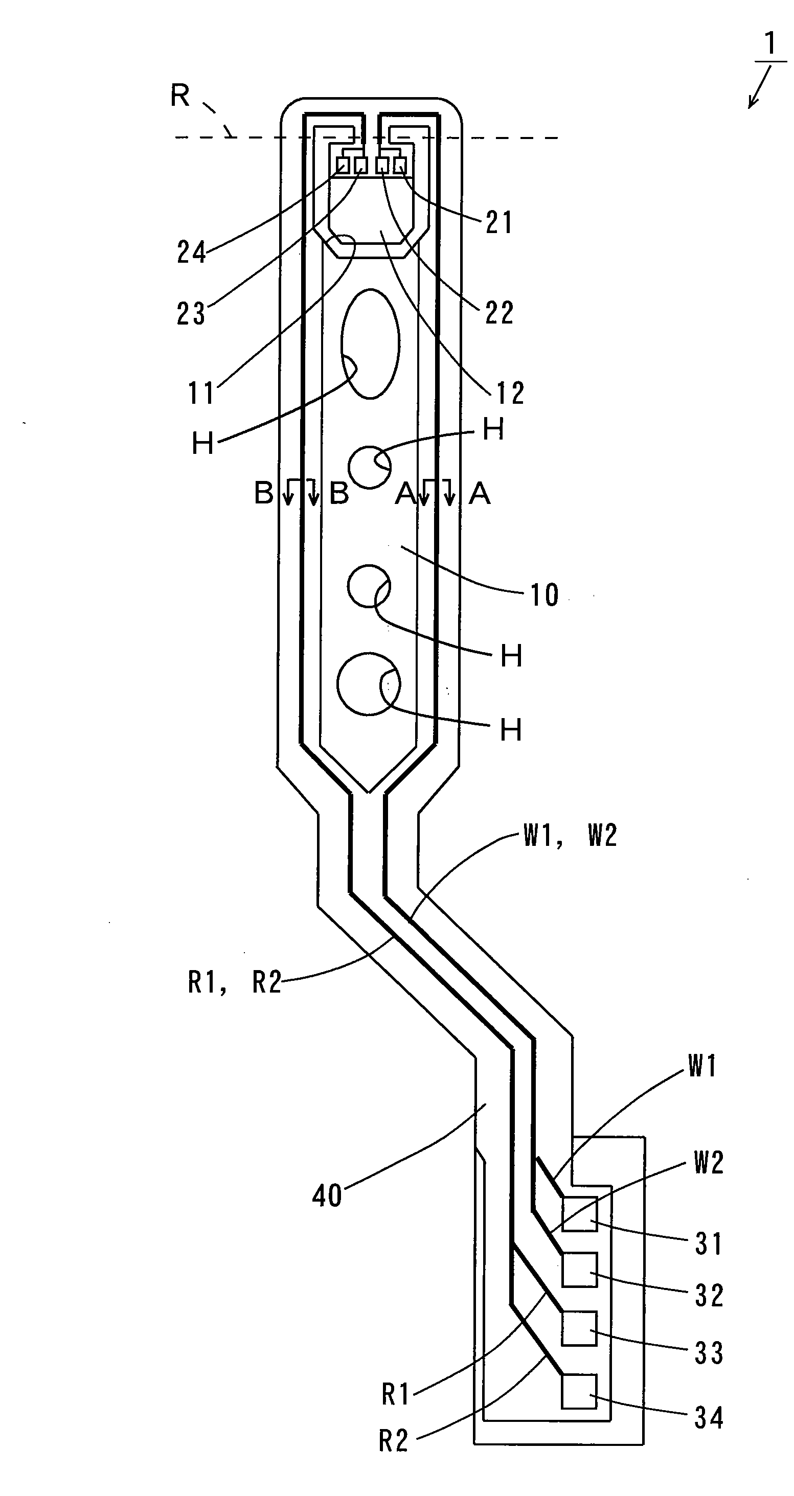
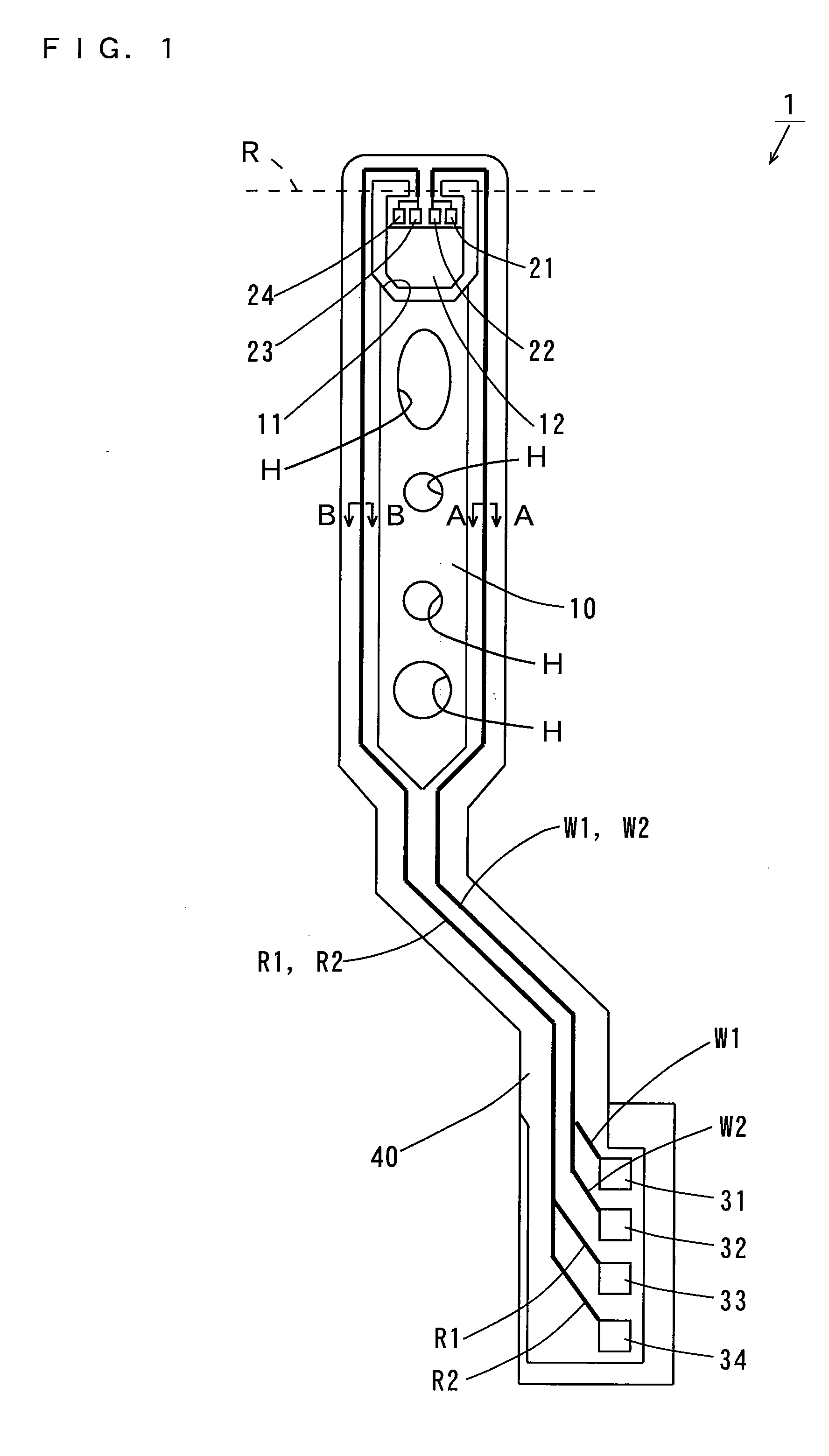
[0046]FIG. 1 is a top view of the suspension board according to a first embodiment of the present invention.

[0047]As shown in FIG. 1, the suspension board 1 includes a suspension body 10 formed of a long-sized metal substrate. Write wiring traces W1, W2 for writing information in a magnetic disk that is not shown and the read wiring traces R1, R2 for reading information from the magnetic disk are formed on the suspension body 10, as indicated by the bold solid lines.

[0048]At an end of the suspension body 10, a U-shaped opening 11 is formed, thereby providing a magnetic head supporting portion (hereinafter referred to as a tongue) 12. The tongue 12 is bent along the broken line R to form a predetermined angle with respect to the suspension body 10. Four electrode pads 21, 22, 23, 24 are formed at an end of the tongue 12.

[0049]Four electrode pads 31, 32, 33, 34 are formed at the other end of the suspension body 10. The electrode pads 21 t...

second embodiment

[0087]FIG. 5 is a vertical sectional view showing a suspension board according to a second embodiment of the present invention.

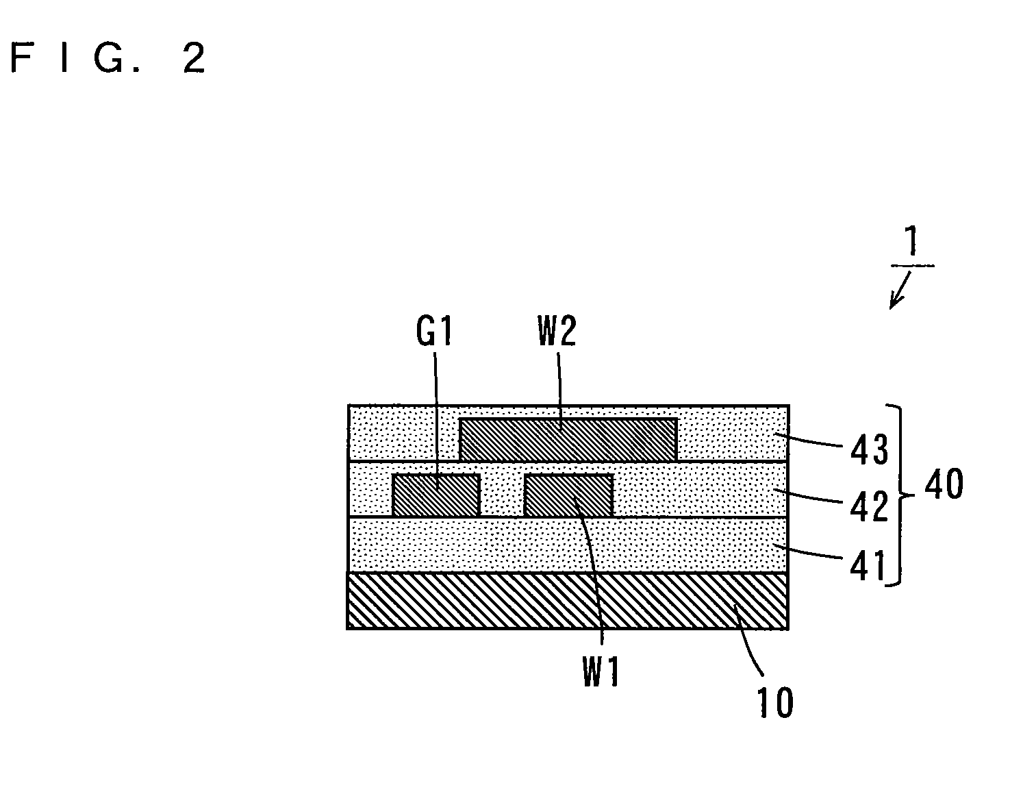
[0088]The suspension board 2 according to the present embodiment is different from the suspension board 1 of FIG. 2 in the following points.

[0089]As shown in FIG. 5, the ground trace G1 is formed on one side of the write wiring trace W1, and a ground trace G2 is formed on the other side of the write wiring trace W1 on the first insulating layer 41 in the present embodiment. The ground trace G2 is formed in the same manner as the ground trace G1.

[0090]Note that the width s5 of the ground trace G2 is set the same as the width s2 (FIG. 3(b)) of the ground trace G1. The spacing d2 between the write wiring trace W1 and the ground trace G2 is set the same as the spacing d1 of FIG. 3(b). The thickness t7 of the ground trace G2 is set the same as the thickness t3 of FIG. 3(b). The width s6 of a region, which is opposite to the ground trace G2, of the write wiring tr...

third embodiment

[0092]FIG. 6 is a vertical sectional view showing a suspension board according to a third embodiment of the present invention.

[0093]The suspension board 3 according to the present embodiment is different from the suspension board 2 of FIG. 5 in the following points.

[0094]As shown in FIG. 6, a ground trace G3 is formed on one side of the write wiring trace W2 while a ground trace G4 is formed on the other side of the write wiring trace W2 on the second insulating layer 42 in the present embodiment. The ground traces G3, G4 are formed in the same manner as the ground trace G1.

[0095]Note that each of the widths s7, s8 of the ground traces G3, G4 is not less than 5 μm and not more than 40 μm, and preferably not less than 10 μm and not more than 30 μm. The thickness t8 of each of the ground traces G3, G4 is set the same as the thickness t5 of FIG. 4(d). Each of the spacing d3 between the ground trace G3 and the write wiring trace W2 and the spacing d4 between the ground trace G4 and the ...


PUM


Abstract

A first insulating layer is formed on a suspension body and a wiring trace is formed on the first insulating layer. In addition, a ground trace is formed on the first insulating layer so as to extend along the wiring trace on one side of the wiring trace with a spacing therebetween. A second insulating layer is formed on the first insulating layer to cover the wiring trace and the ground trace. On the second insulating layer, a wiring trace is formed at a position above the wiring trace. A third insulating layer is formed on the second insulating layer to cover the wiring trace. The width of the wiring trace is set larger than the width of the wiring trace. At least a partial region of the ground trace and at least a partial region of the wiring trace are opposite to each other with part of the second insulating layer sandwiched therebetween.

Description

BACKGROUND OF THE INVENTION[0001]1. Field of the Invention[0002]The present invention relates to a printed circuit board.[0003]2. Description of the Background Art[0004]An actuator is used in a drive such as a hard disk drive. Such an actuator includes an arm arranged rotatably with respect to a rotation shaft and a suspension board used for a magnetic head that is attached to the arm. The suspension board is a printed circuit board for positioning the magnetic head with a desired track of a magnetic disk.[0005]FIG. 11 is a vertical sectional view showing one example of a conventional suspension board. In the suspension board 900 of FIG. 11, an insulating layer 903 is formed on a metal substrate 902. A pair of write conductors W1, W2 and a pair of read conductors R1, R2 are formed so as to be arranged in sequence on the insulating layer 903.[0006]One ends of the conductors W1, W2, R1, R2 are connected to a magnetic head (not shown). The other ends of the conductors W1, W2, R1, R2 ar...

Claims


Application Information

Patent Timeline
IPC IPC(8): H05K1/00
CPCG11B5/486H05K1/0219H05K1/0245H05K1/0248H05K2201/09727H05K2201/0352H05K2201/09236H05K2201/09672H05K1/056G11B5/484
Inventor HO, VOONYEEKAMEI, KATSUTOSHI
Owner NITTO DENKO CORP
Why Eureka
Try Eureka