
Device and arrangement for fixture installation

a fixture and device technology, applied in the field of devices and arrangements for fixture installation, can solve the problems of inability to obtain the precise position of the fixture in the jaw bone, poor or impossible fitting of the dental bridge, and the inability to produce the bridge to be applied to the fixture, so as to avoid reconfiguration and extra costs.

Inactive Publication Date: 2009-10-08
NOBEL BIOCARE SERVICES AG
View PDF86 Cites 53 Cited by
  • Summary
  • Abstract
  • Description
  • Claims
  • Application Information

AI Technical Summary

Benefits of technology

The present invention relates to a device and arrangement for installation of fixtures in a jaw bone. The invention aims to solve problems such as incomplete or incorrect positioning of fixtures in the jaw bone, which can result in poor fitting of dental bridges. The invention provides a fixture holder with elements that can be used to define the position of the fixture in the vertical and transverse directions in the jaw bone, ensuring precise installation. The invention also addresses the problem of soft tissue growth over the exposed fixture end, which can make it difficult to identify the bone structure during bridge installation. The invention includes a fixture holder designed to cooperate with a guide member forming part of a template, ensuring defined positions of the fixture in the jaw bone. The invention provides a solution that can easily be incorporated into existing techniques without requiring reconfiguration or extra costs.

Problems solved by technology

In installation work performed by practiced doctors, it sometimes happens that the separate device is not used, which means there is a risk that the necessarily precise positions of the fixtures in the jaw bone will not be obtained.
Without using the separate device (fixture guide), the fixtures can easily end up in positions which are too deep, with the result that the produced bridge which is to be applied to the fixtures does not fit them.
This too can result in poor or impossible fitting of the dental bridge which is to be installed.
In fixture installations using previously known auxiliary devices, problems can also arise if the installation work is drawn out over time.
Given said time consideration, this means that soft tissue parts of the jaw bone can start to grow over the implant in a relatively short time, so that these become difficult to identify in the subsequent bridge installation work.

Method used


Image

  • Device and arrangement for fixture installation
  • Device and arrangement for fixture installation

Examples


Embodiment Construction

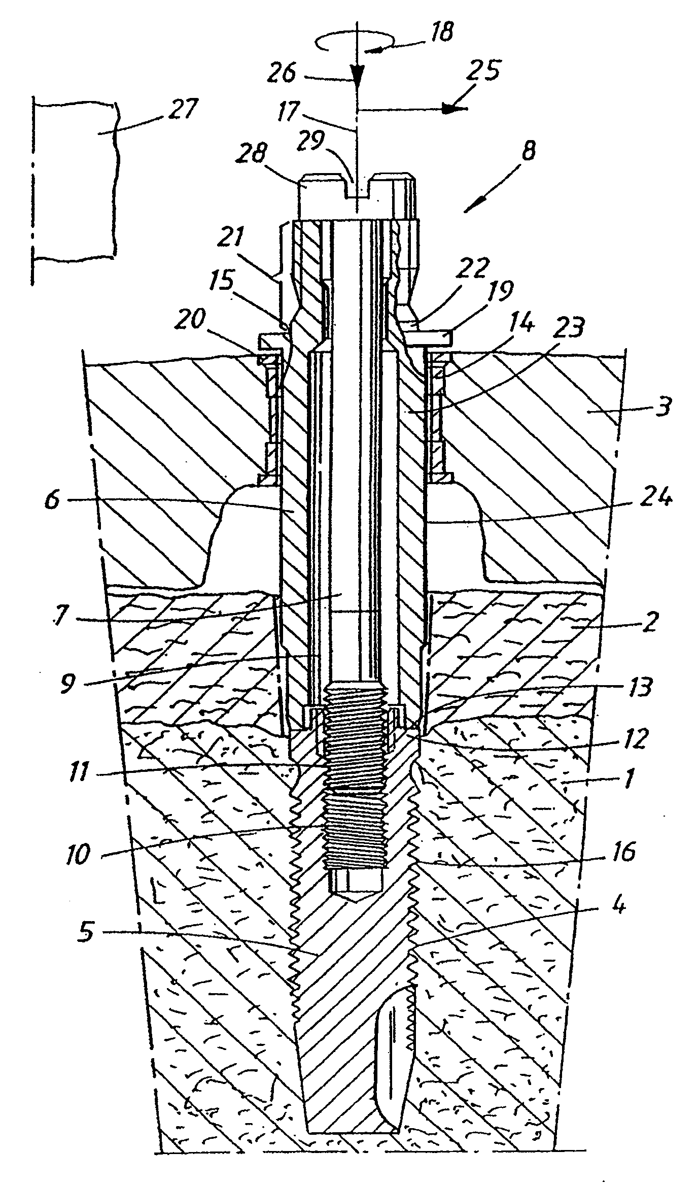
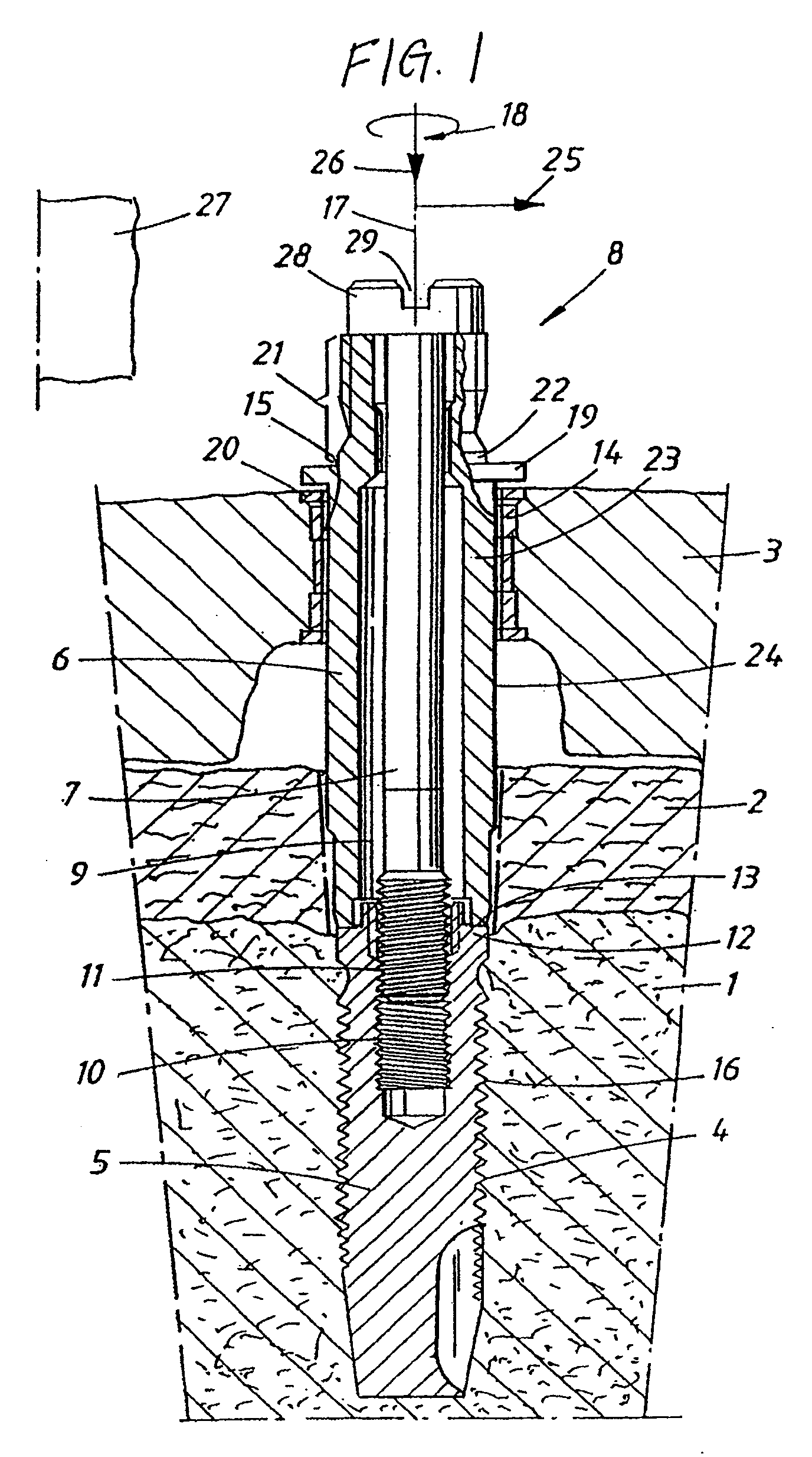
[0016]In the FIGURE, reference number 1 designates a jaw bone, and reference number 2 designates gum (mucosa) or soft tissue. A template of a type known per se is arranged on top of the soft tissue, in which connection reference may be made to the PCT specifications mentioned above. A hole / drilled hole 4 has been formed in the jaw bone in a manner known per se. A fixture 5 has been applied in the hole, and the application has been performed with the aid of a fixture holder 6 which assumes an assembled state with the fixture, which state has been obtained with the aid of a screw 7 extending from the upper parts 8 of the fixture holder, through the fixture holder in an inner recess 9 formed therein, and down into a thread 10 in the fixture. The screw 7 is provided with an outer thread 11 via which the screw can be screwed into the thread 10 of the fixture which is an inner thread. The fixture is provided with an upper flange 12 against which an end surface 13 of the fixture holder 6 c...


PUM


Abstract

A device and arrangement for installation of a fixture in a jaw bone comprises a fixture holder designed to cooperate with a guide member forming part of a template, via which guide member the fixture can be applied in its position in the jaw bone with the aid of the fixture holder. The arrangement is also provided with one or more elements which, with the aid of the guide member, ensure defined positions of the fixture in the vertical and transverse directions. The element or elements is or are arranged on the fixture holder.

Description

CROSS-REFERENCE TO RELATED APPLICATIONS[0001]This application is a continuation of U.S. patent application Ser. No. 11 / 172,291 filed on Jun. 30, 2005, which is a continuation of International Application PCT / SE2003 / 001975, with an international filing date of Dec. 17, 2003, which claims priority under 35 U.S.C. § 119 to Swedish Patent Application No. SE 0203898-2, filed Dec. 30, 2002, the entire contents of each of which are expressly incorporated by reference herein.BACKGROUND OF THE INVENTION[0002]1. Field of the Invention[0003]The present invention relates to a device and arrangement for installation of a fixture in a jaw bone. The invention also relates to an arrangement for installation of two or more fixtures which can be installed in the jaw bone in a corresponding manner.[0004]2. Description of the Related Art and Summary of the Invention[0005]Embodiments of the present invention re intended to be used in, among other things, the arrangement sold by Nobel Biocare AB for ARK ...

Claims


Application Information

Patent Timeline
Patent Type & Authority Applications(United States)
IPC IPC(8): A61C8/00A61C1/08
CPCA61C8/0089A61C1/084
Inventor BRAJNOVIC, IZIDOR
Owner NOBEL BIOCARE SERVICES AG
Learn More