Endoscope, connection method of bending section and flexible section in endoscope, production method of endoscope provided for this connection method, endoscope overtube, connection method of bending section and flexible section in endoscope overtube and production method of endoscope overtube provided for this connection method
- Summary
- Abstract
- Description
- Claims
- Application Information
AI Technical Summary
Benefits of technology
Problems solved by technology
Method used
Image

Examples
first embodiment
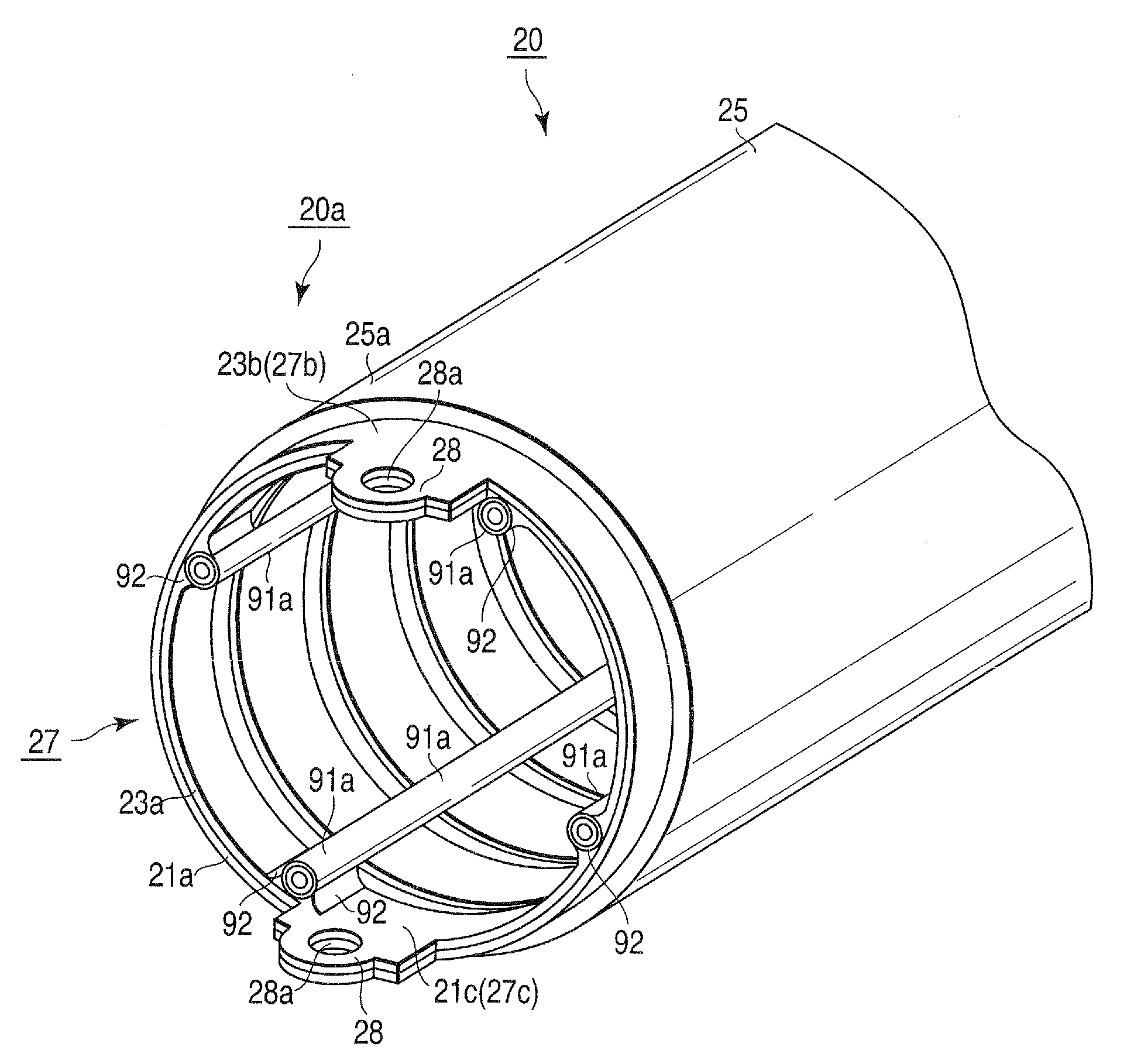
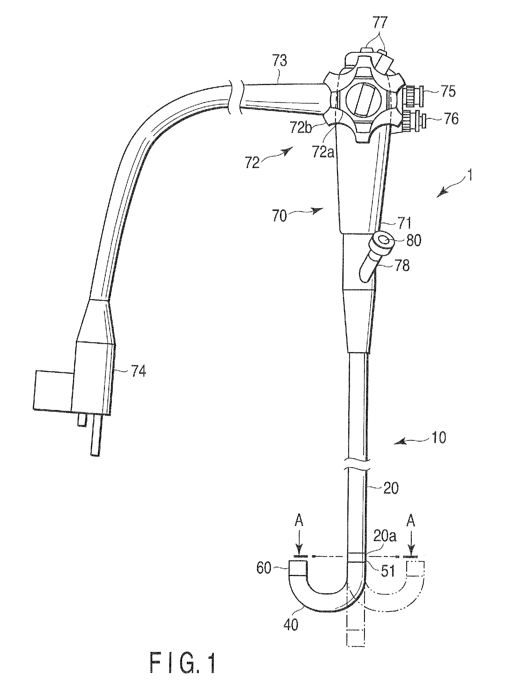
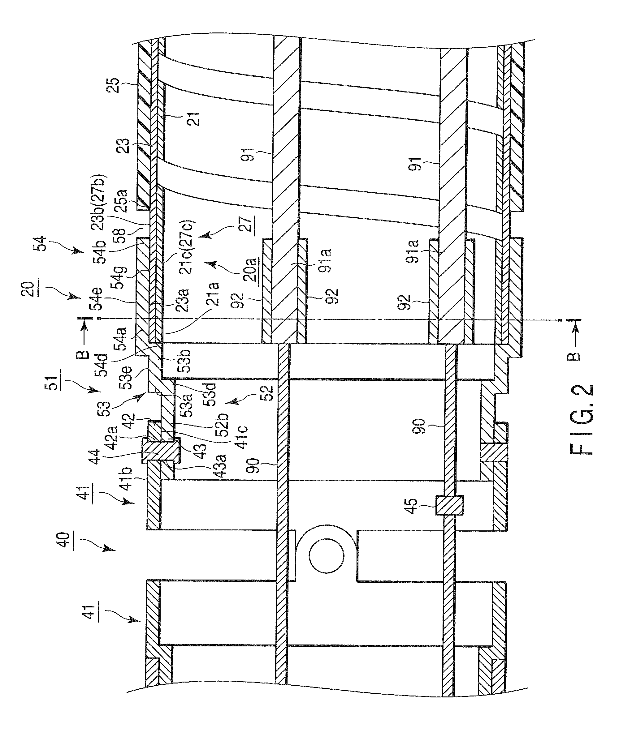
[0042]A first embodiment will be explained with reference to FIGS. 1 to 7 and FIG. 8A. It should be noted that tubular members and others are partially omitted in FIG. 2.
[0043]As shown in FIG. 1, an endoscope 1 has an elongated insertion section 10 that is inserted into, e.g., a body cavity of a patient and an operating section 70 that is coupled to a proximal end of the insertion section 10 and operates a later-explained bending section 40 of the insertion section 10.
[0044]In the operating section 70 are provided a grasping section 71 grasped by an operator and a bending operation knob 72 that bends the bending section 40.
[0045]A proximal end portion of a universal cord 73 is coupled to the grasping section 72. A connector section 74 connected with a non-illustrated light source device or a video processor is coupled to a distal end portion of this universal cord 73.
[0046]In a bending operation knob 72 are provided a lateral bending operation knob 72a that operates the bending sect...
second embodiment
[0114]A second embodiment according to the present invention will now be explained with reference to FIG. 10. It should be noted that the same reference numbers as those in the first embodiment denote the same structures as those in the first embodiment, obviating explanation thereof.
[0115]Although the distal end 91a is fixed to the inner peripheral surface 27c (inner peripheral surface 21c), i.e., the distal end 20a of the flexible section 20 in the first embodiment, the present invention does not have to be restricted thereto. For example, the distal end 91a may be fixed to the inner peripheral surface 51c of the node ring 51. In more detail, for example, the same excess metal portion 92 as that in the first embodiment is formed on the inner peripheral surface 52g of the distal end portion 52. The distal end 91a is fixed to the inner peripheral surface 52g, i.e., the inner peripheral surface 51c when secured to the excess metal portion 92. In other words, the distal end 91a is fix...
third embodiment
[0118]A third embodiment according to the present invention will now be explained with reference to FIGS. 11A and 11B. It should be noted that reference numbers the same as those in the first embodiment denote structures equivalent to those in the first embodiment, obviating explanation thereof.
[0119]A flexible section 20 and a bending section 40 in this embodiment are directly coupled to each other to allow them to swivel motion when a flexible tube side hard section 27 is fitted into a node ring 51 and the flexible tube side hard section 27 is coupled to the node ring 51 by spindle sections (e.g., rivets 44 as swiveling members) to allow them to swivel.
[0120]As shown in FIG. 11A, in the flexible section 20, a distal end 21a and a distal end 23a are extended toward a distal end 20a side of the flexible section 20 by the desired same length beyond a distal end 25a as in the first embodiment. Therefore, an outer peripheral surface 23b is exposed. Later-explained protruding pieces 42 ...
PUM
| Property | Measurement | Unit |
|---|---|---|
| Diameter | aaaaa | aaaaa |
| Flexibility | aaaaa | aaaaa |
Abstract
Description
Claims
Application Information
 - Generate Ideas
- Intellectual Property
- Life Sciences
- Materials
- Tech Scout
- Unparalleled Data Quality
- Higher Quality Content
- 60% Fewer Hallucinations
Browse by: Latest US Patents, China's latest patents, Technical Efficacy Thesaurus, Application Domain, Technology Topic, Popular Technical Reports.
© 2025 PatSnap. All rights reserved.Legal|Privacy policy|Modern Slavery Act Transparency Statement|Sitemap|About US| Contact US: help@patsnap.com