Low insertion force connector assembly and semiconductor component test apparatus

Active Publication Date: 2020-03-26
CHEMITECH CORP
View PDF0 Cites 0 Cited by
  • Summary
  • Abstract
  • Description
  • Claims
  • Application Information

AI Technical Summary

Benefits of technology

[0059]According to the present invention, the low insertion force connector assembly and the semiconductor component test apparatus can achieve easy and rigid coupling between the first connector and the second connector to prevent occurrence of poor contacts, simple

Problems solved by technology

If the pressurizing forces are strong, electrical contacts become increased, but frictional forces are also big, so that it is hard to insert or separate the connection component into or from the connector.
Accordingly, the contacted states of the contacts may be poor or the coupled state between the connectors may be released according to external forces applied to the connectors.
As the number of contacts of the connectors is increased, further, an insertion force needed for coupling the connectors becomes large and the coupling process b

Method used


Image

  • Low insertion force connector assembly and semiconductor component test apparatus
  • Low insertion force connector assembly and semiconductor component test apparatus
  • Low insertion force connector assembly and semiconductor component test apparatus

Examples


Example

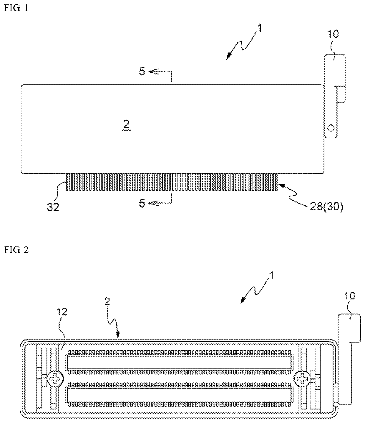
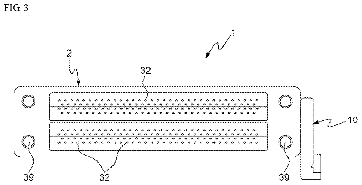
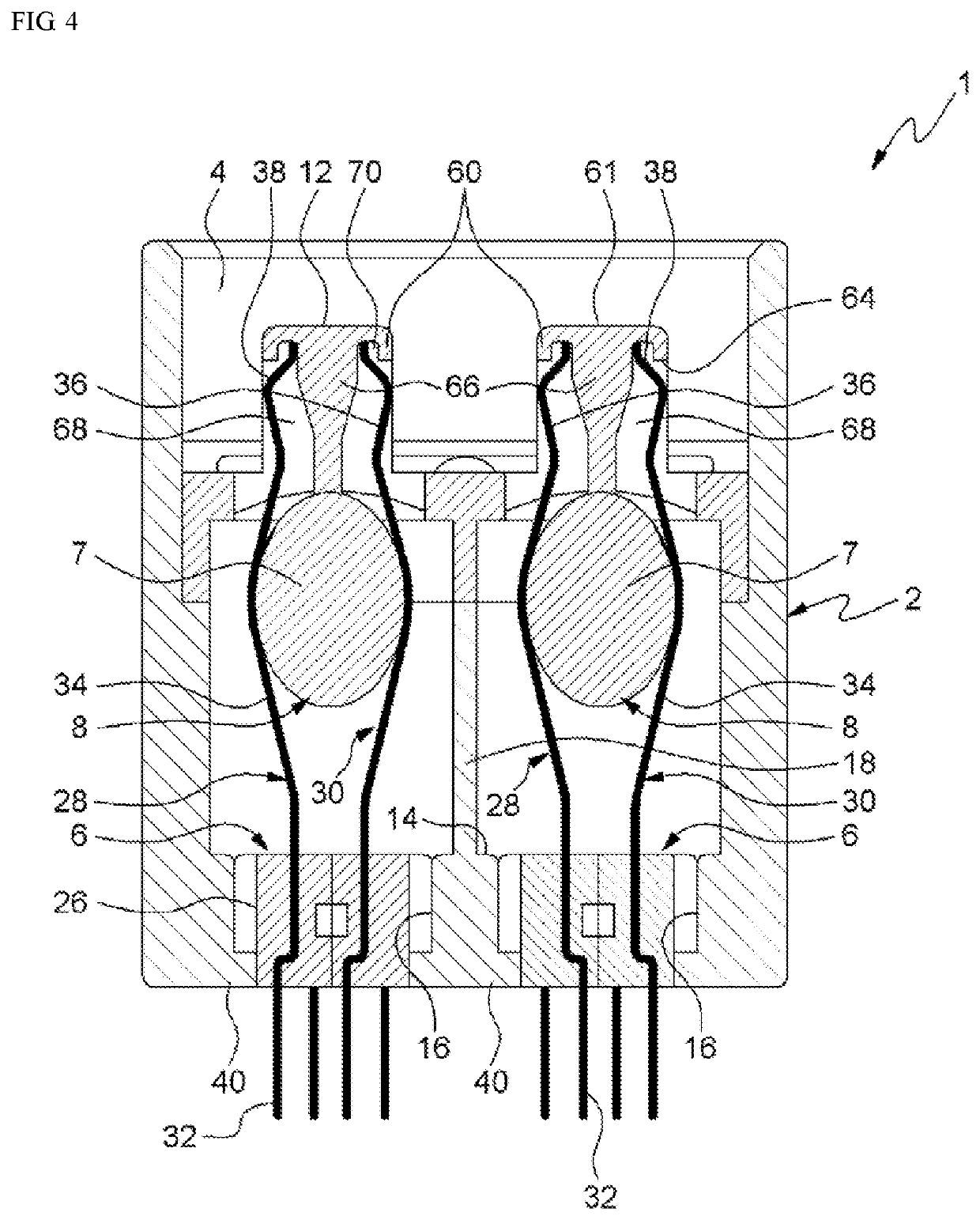
[0097]Hereinafter, a low insertion force connector assembly according to the present invention will be in detail explained with reference to the attached drawing.

[0098]FIG. 10 is a perspective view showing a first connector of a low insertion force connector assembly according to the present invention, FIG. 11 is a front view showing an outer member of the first connector of FIG. 10, FIG. 12 is a perspective view showing the outer member of the first connector of FIG. 10, FIG. 13 is a perspective view showing an intermediate member of the first connector of FIG. 10, FIGS. 14 and 15 are perspective views showing a pin module of the first connector of FIG. 10, FIG. 16 is a perspective view showing a bottom of a top member of the first connector of FIG. 10, FIG. 17 is a perspective view showing the top member, driving shafts, and handles of the first connector of FIG. 10, FIGS. 18 and 19 are perspective views showing a state where the pin module is coupled to the outer member of the fi...


PUM


Abstract

A low insertion force connector assembly includes a first connector and a second connector which are detachably coupled to each other, wherein the first connector and the second connector are easily assembled to prevent contact failure and are firmly assembled to each other to improve dimensional stability, and it is easy to assemble and manufacture the connectors.

Description

TECHNICAL FIELD[0001]The present invention relates to a low insertion force connector assembly and a semiconductor component test apparatus, and more particularly, to a low insertion force connector assembly and a semiconductor component test apparatus that are capable of achieving rigid and simple coupling between a first connector and a second connector and stable contacts between connector pins and contact pins.BACKGROUND ART[0002]So as to allow a connector and a connection component mounted onto the connector to be electrically connected to each other reliably, connector pins of the connector and electrical terminals of the connection component have to be pressurized against each other. If the pressurizing forces are strong, electrical contacts become increased, but frictional forces are also big, so that it is hard to insert or separate the connection component into or from the connector. If a plurality of pins is mounted on the connector or if connection components are inserte...

Claims


Application Information

Patent Timeline
IPC IPC(8): G01R31/28H01R12/83H01R13/639H01R13/64
CPCH01R13/639G01R31/28H01R12/83H01R13/64H01R12/82G01R1/0408H01R2201/20H01R13/193
Inventor PARK, JOONEONAN, SANGIL
Owner CHEMITECH CORP
Why Eureka
Try Eureka