Cooled lighting system

a cooling and lighting technology, applied in the field of lighting systems, can solve the problems of not always so robust leds, and achieve the effect of easy couples

Active Publication Date: 2021-05-13
AVID LABS LLC
View PDF0 Cites 0 Cited by
  • Summary
  • Abstract
  • Description
  • Claims
  • Application Information

AI Technical Summary

Benefits of technology

[0011]Advantageously, the present invention provides a lighting system that easily couples to a cooling pipe.

Problems solved by technology

LEDs were not always so robust when they were developed in 1962.

Method used


Image

  • Cooled lighting system
  • Cooled lighting system

Examples


Embodiment Construction

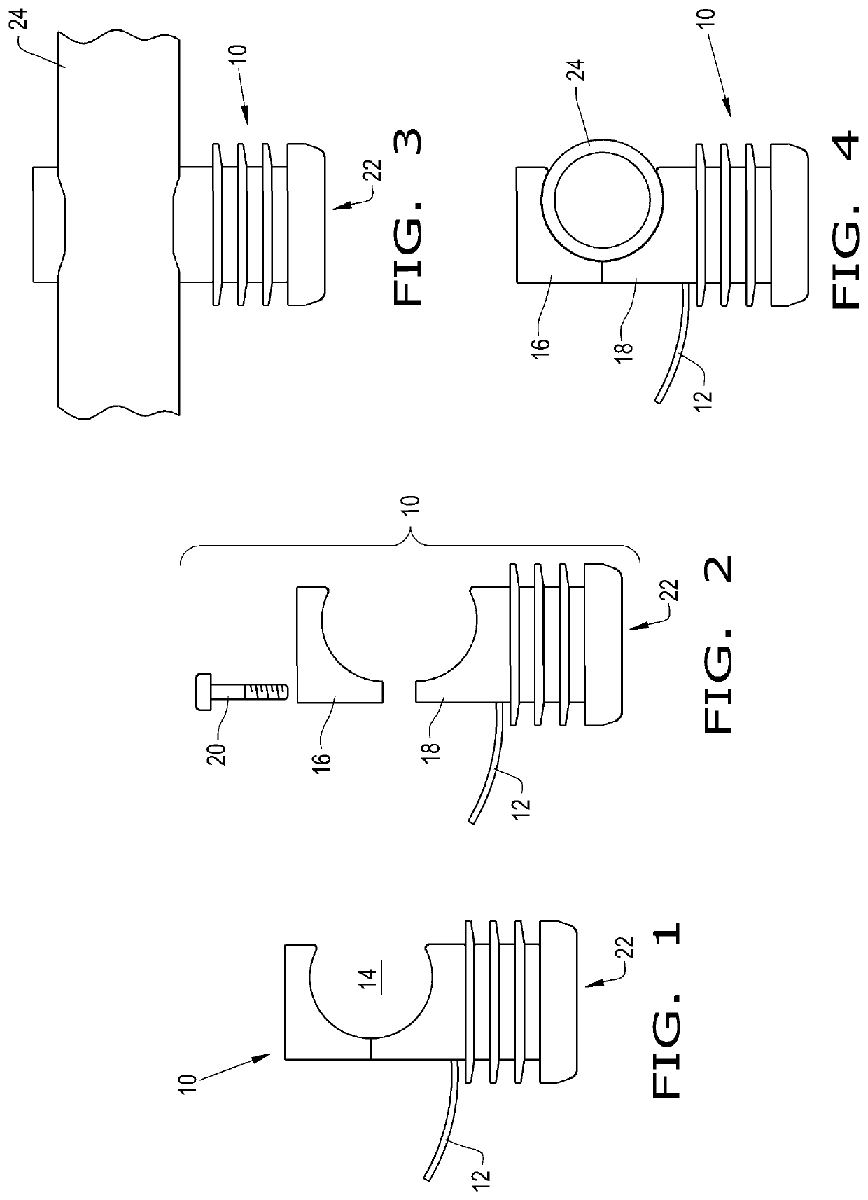
[0021]Referring now to the drawings, and more particularly to FIG. 1, there is shown, a side view of a light fixture 10 having an electrical connection 12, in the form of wiring 12, and a clamping area 14. Referring to FIG. 2 there is shown light fixture 10 in an exploded view, in which upper portion 16 and lower portion 18 are shown along with a screw 20. Light fixture 10 is designed to produce a large amount of light for the growing of plants. The intensity of the light emanating from light fixture 10 is such that cooling of the light producing element 22 is needed.

[0022]Now, additionally referring to FIG. 3 there is shown a pipe 24, with light fixture 10 clamped thereto using clamping area 14 to encompass more than half of the circumference of pipe 24. The presence of pipe 24 allows for a transfer of heat from light producing element 22 to thereby allow light producing element 22 to more effectively produce the needed level of light. The thermal coupling from element 22 to pipe 2...


PUM


Abstract

A lighting system includes a plurality of lighting fixtures coupled to a cooling pipe, each lighting fixture having an open sided pipe coupling portion and a lighting member connected to the coupling portion. The lighting member being thermally coupled to an inside portion of the pipe coupling portion. The lighting member having a light emanating away from the cooling pipe.

Description

CROSS REFERENCE TO RELATED APPLICATIONS[0001]This is a non-provisional application based upon U.S. provisional patent application Ser. No. 62 / 934,790 entitled “COOLED LIGHTING SYSTEM”, filed Nov. 13, 2019, which is incorporated herein by reference.BACKGROUND OF THE INVENTION1. Field of the Invention[0002]The present invention relates to a lighting system that provides a high intensity of light and is cooled by way of a connection with its mounting feature.2. Description of the Related Art[0003]High intensity lighting is needed in particular applications, such as for use in plant raising facilities, such as a greenhouse. High intensity efficient lighting by way of light emitting diodes (LEDs), even though very efficient still produces waste heat, which needs to be conducted away from the LED to prevent degradation and failure of the LED.[0004]LEDs were not always so robust when they were developed in 1962. The earliest LEDs emitted low-intensity infrared light and were often used in ...

Claims


Application Information

Patent Timeline
Patent Type & Authority Applications(United States)
IPC IPC(8): F21V29/50F21V21/088A01G9/24A01G7/04
CPCF21V29/50F21V21/088A01G9/249A01G7/045A01G9/247F21V29/59F21S2/005F21Y2115/20F21S4/28Y02A40/25Y02P60/14
Inventor NICHOLS, JOEL A.
Owner AVID LABS LLC
Why Eureka
Try Eureka