Implantable sensor lead

a sensor and lead technology, applied in the field of implantable sensor leads, can solve the problems of difficult to freely select the placement of the sensor element the mechanical sensor element carrying, and the disturbance of the cardiac sensor,

Active Publication Date: 2009-10-08
ST JUDE MEDICAL
View PDF7 Cites 0 Cited by
  • Summary
  • Abstract
  • Description
  • Claims
  • Application Information

AI Technical Summary

Problems solved by technology

Leads carrying mechanical sensor elements, like accelerometers, pressure sensing elements, strain gauges or tensiometers, often suffer from disturbances caused by local forces acting on the sensor elements.
Similar problems occur in connection with the use of so-called CMES-sensors, Cardio Mechanical Sensors, placed in the right ventricle, in coronary sinus, in great cardiac vein or in a coronary vein.
Moreover, the placement of the sensor element of a cardiac sensor is seldom freely selectable.

Method used


Image

  • Implantable sensor lead
  • Implantable sensor lead
  • Implantable sensor lead

Examples


Embodiment Construction

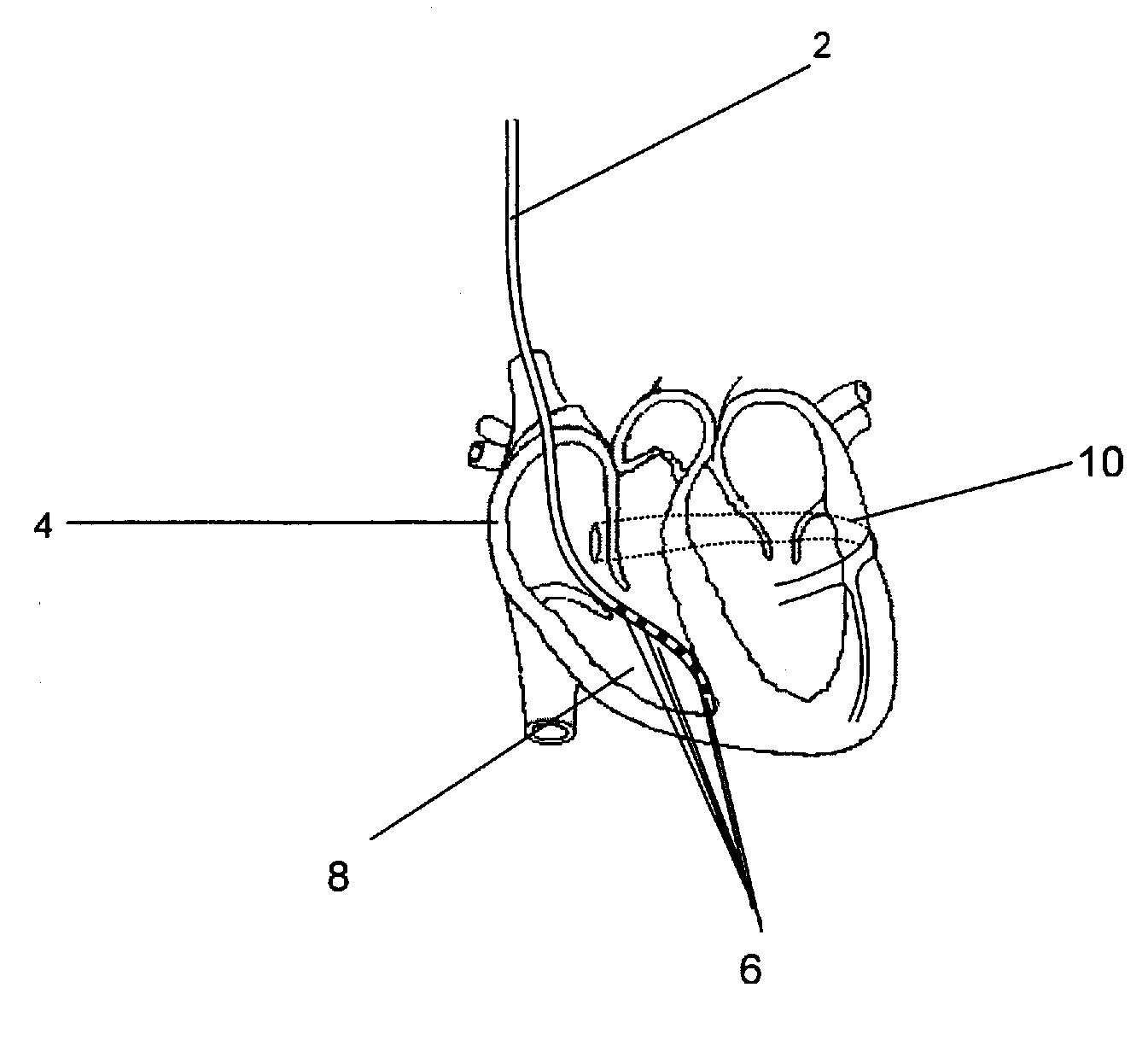
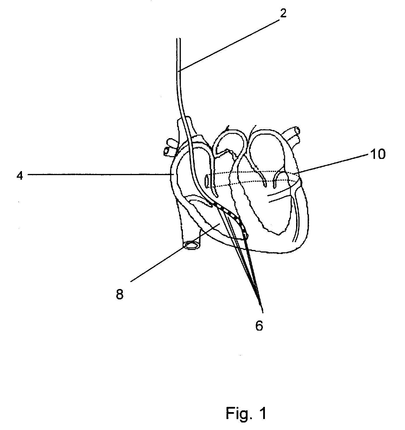
[0018]FIG. 1 shows a lead 2 implanted in a person's heart 4 with a plurality of sensing elements 6 located in the right ventricle 8 of the heart 4. The sensing elements 6 are distributed along a part of the lead body for sensing cardiac activity from a larger part or a larger volume of the right ventricle 8

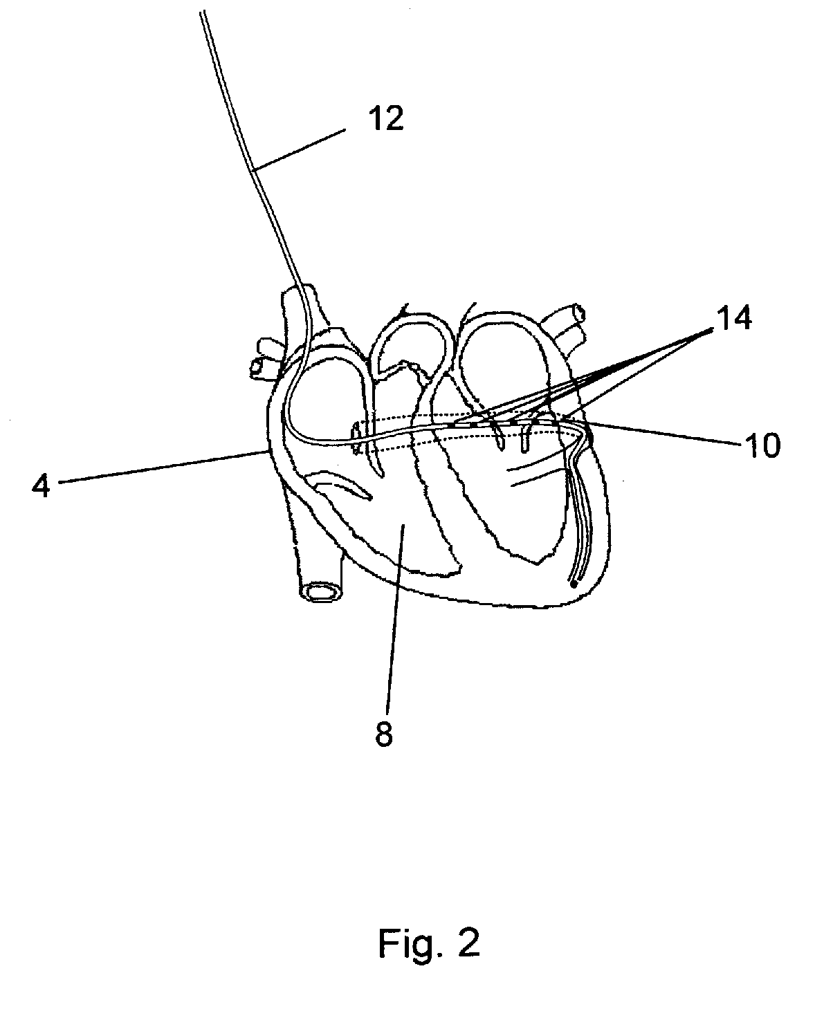
[0019]FIGS. 2 and 3 show two embodiments of the lead according to the invention implanted in a coronary vein 10 on the left side of the heart 4. The lead 12 shown in FIG. 2 is provided with a plurality of sensing elements 14 distributed along a part of the lead body adapted for implantation in the Coronary sinus for sensing the movement of the valve plane of the heart 4. The movement of the valve plane can reveal diastolic heart failure. The lead 18 shown in FIG. 3 is provided with a plurality of sensing elements 20 distributed along a part of the lead body adapted for sensing mechanical cardiac activity in the left ventricle 22 of the heart 4.

[0020]In the embodiments illustrated ...


PUM


Abstract

In an implantable sensor lead for sensing mechanical cardiac activity of a heart, as well as a sensing method and a cardiac stimulator embodying such a sensor lead, multiple cardiac activity sensing elements are distributed along a portion of a length of the lead body of the implantable lead. The sensing elements sense or detect mechanical cardiac activity and respectively emit electrical signals corresponding to the detected mechanical cardiac activity. The delivery of cardiac stimulation pulses can be controlled dependent on an analysis of the detected mechanical cardiac activity.

Description

BACKGROUND OF THE INVENTION[0001]1. Field of the Invention[0002]The present invention relates to an implantable sensor lead for sensing mechanical cardiac activity of a person, to an electronic device, an implantable cardiac stimulator as well as a method for sensing mechanical cardiac activity of a person.[0003]2. Description of the Prior Art[0004]Sensor signals can be used for purposes such as optimization of biventricular synchronization or setting the AV-delay in connection with cardiac stimulation, diagnosis of congestive heart failure, etc.[0005]Leads carrying mechanical sensor elements, like accelerometers, pressure sensing elements, strain gauges or tensiometers, often suffer from disturbances caused by local forces acting on the sensor elements. Thus, such a sensor element placed on e.g. the left side of the heart in a coronary vein is heavily influenced by local forces close to the sensor element. Similar problems occur in connection with the use of so-called CMES-sensors,...

Claims


Application Information

Patent Timeline
Patent Type & Authority Applications(United States)
IPC IPC(8): A61B5/02
CPCA61B5/0422A61B5/053A61N2001/0585A61N1/3627A61N1/365A61N1/056A61B5/287
Inventor SVEN-ERIK, HEDBERGLAGERCRANTZ, PER
Owner ST JUDE MEDICAL
Why Eureka
Try Eureka