Method for providing a temporary barrier in a flow pathway

a flow pathway and temporary barrier technology, applied in the direction of sealing/packing, drilling pipes, borehole/well accessories, etc., can solve the problems of mud invasion into the formation, poor drilling mud performance, and formation damage to debris

Active Publication Date: 2009-10-15
BAKER HUGHES INC
View PDF16 Cites 114 Cited by
  • Summary
  • Abstract
  • Description
  • Claims
  • Application Information

AI Technical Summary

Benefits of technology

[0009]There is provided, in one form, a downhole filtration tool that has a flow conduit with a plurality of orifices, a degradable barrier in the orifices, and a delayed degradation material layer over the degradable barrier. The degradable barrier degrades into at least one product such as an acid, a base, an alcohol, carbon dioxide and combinations thereof. The delayed degradation material layer degrades at a rate slower than the degradable barrier. Optionally, th

Problems solved by technology

Optionally, the product may also remove some or all materials including, but not necessarily limited to, potentially formation damaging debris left from perforat

Method used


Image

  • Method for providing a temporary barrier in a flow pathway
  • Method for providing a temporary barrier in a flow pathway
  • Method for providing a temporary barrier in a flow pathway

Examples


Embodiment Construction

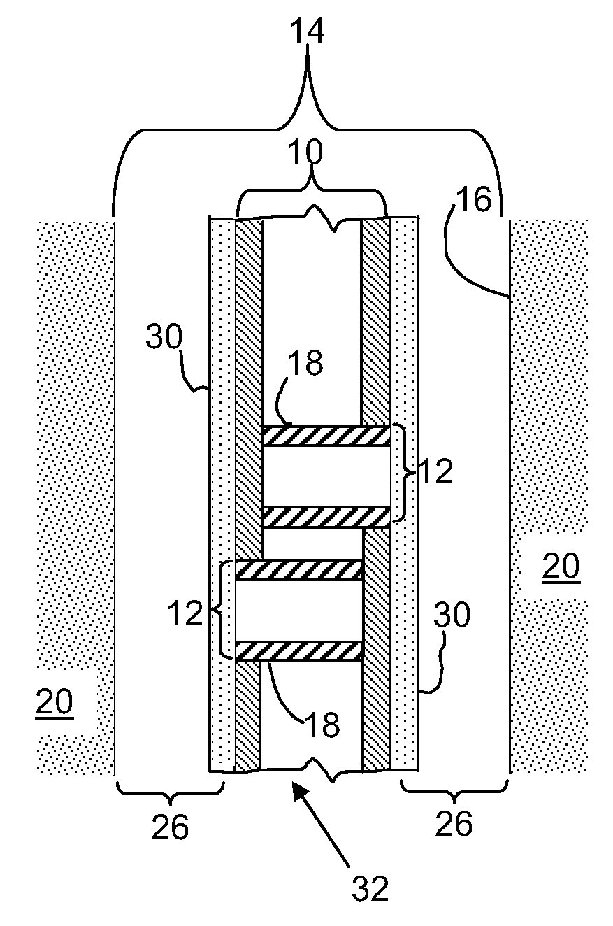
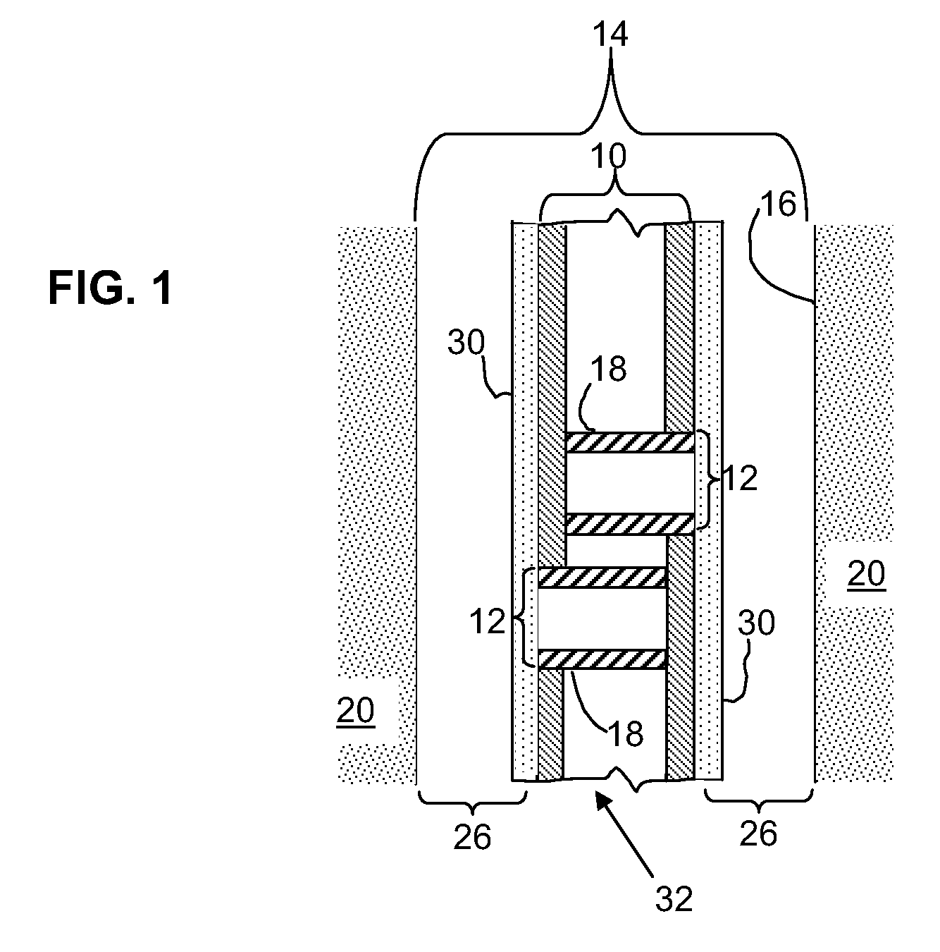
[0016]It has been discovered, in one non-limiting embodiment, that biodegradable polymers or other degradable or reactive materials may effectively serve as temporary barriers, films, coatings and the like on downhole filtration tools, such as sand control screens. Optionally, the degradable barriers may degrade, disintegrate or decompose into products that in turn can remove a temporary coating, such as a drill-in fluid filter cake breaker for oil well, gas well or injection well completion methods. However, as noted elsewhere herein, the method is not limited to this particular embodiment. For instance, the decomposition or degradation product may also subsequently remove materials including, but not necessarily limited to, formation damaging debris left from perforating operations in case-hole completions and other operations and mud placed by undesirable mud invasion due to poor drilling mud performance.

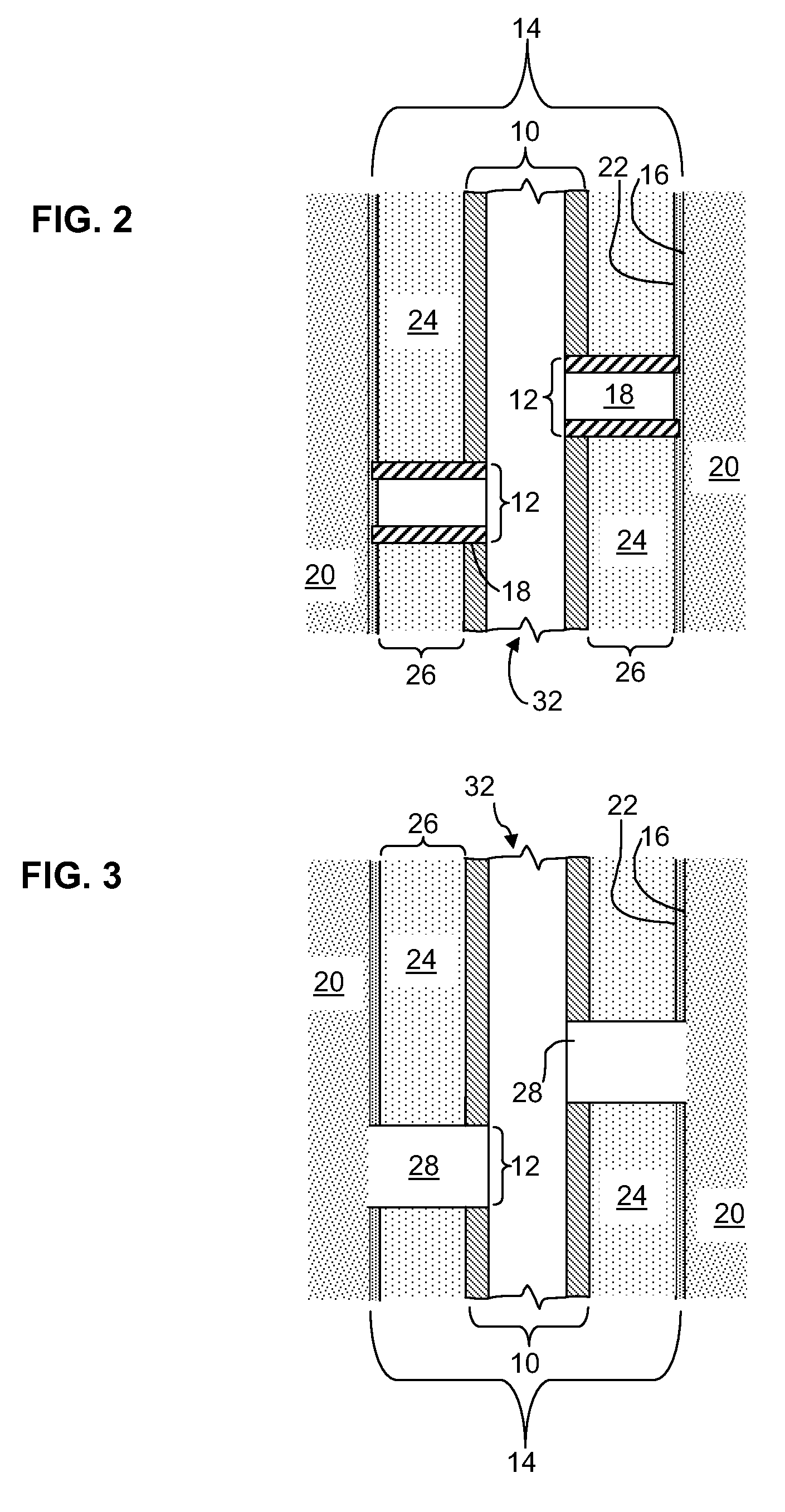
[0017]In another non-limiting form, the method may include wrapping a film o...


PUM


Abstract

A flow conduit may have at least one orifice, which conduit is in the vicinity of a flow source. The source is at least partially covered (and flow blocked by) an optional temporary coating or barrier (e.g. filter cake). The flow pathway between the orifice and the source is temporarily blocked with a degradable material. A delayed degradation material layer is present over or covering the degradable material. The delayed degradation material layer degrades at a rate slower than the degradable barrier. The degradable material and delayed degradation material layer disintegrate (e.g. via time, temperature, a solvent). The degradable material optionally produces a product that removes the temporary coating. The method is useful in one context of recovering hydrocarbons where the flow conduit is the casing or liner of the well and the flow source is a subterranean reservoir where the coating is filter cake.

Description

CROSS-REFERENCE TO RELATED APPLICATIONS[0001]This application is a continuation-in-part application from U.S. patent application Ser. No. 12 / 328,449 filed Dec. 4, 2008, which is a divisional from U.S. patent application Ser. No. 10 / 968,534 filed Oct. 19, 2004, which issued as U.S. Pat. No. 7,461,699 B2 on Dec. 9, 2008, which in turn claimed the benefit of U.S. provisional patent application No. 60 / 513,425 filed Oct. 22, 2003.TECHNICAL FIELD[0002]The present invention relates to methods, compositions and apparatus for temporarily blocking a flow pathway, and more particularly relates, in one non-limiting embodiment, to methods, compositions and apparatus for temporarily blocking a flow pathway to subterranean formations during hydrocarbon recovery operations that may deploy a downhole filtration tool.BACKGROUND[0003]There are a number of procedures and applications that involve the formation of a temporary seal, barrier or plug while other steps or processes are performed, where the ...

Claims


Application Information

Patent Timeline
IPC IPC(8): E21B43/08E21B43/10E21B29/00E21B29/02
CPCE21B37/06E21B43/086E21B43/02
Inventor RICHARD, BENNETT M.MCELFRESH, PAUL M.WILLIAMS, CHAD F.
Owner BAKER HUGHES INC
Why Eureka
Try Eureka