Battery charging control circuit

Inactive Publication Date: 2009-10-15
HONG FU JIN PRECISION IND (SHENZHEN) CO LTD +1
View PDF12 Cites 14 Cited by
  • Summary
  • Abstract
  • Description
  • Claims
  • Application Information

AI Technical Summary

Problems solved by technology

However, in either the CC mode or the CV mode, battery charging is terminated once the battery's voltage reaches a peak value (e.g., 4.2 V), which may result in the battery not being fully charged.

Method used


Image

  • Battery charging control circuit
  • Battery charging control circuit
  • Battery charging control circuit

Examples


Embodiment Construction

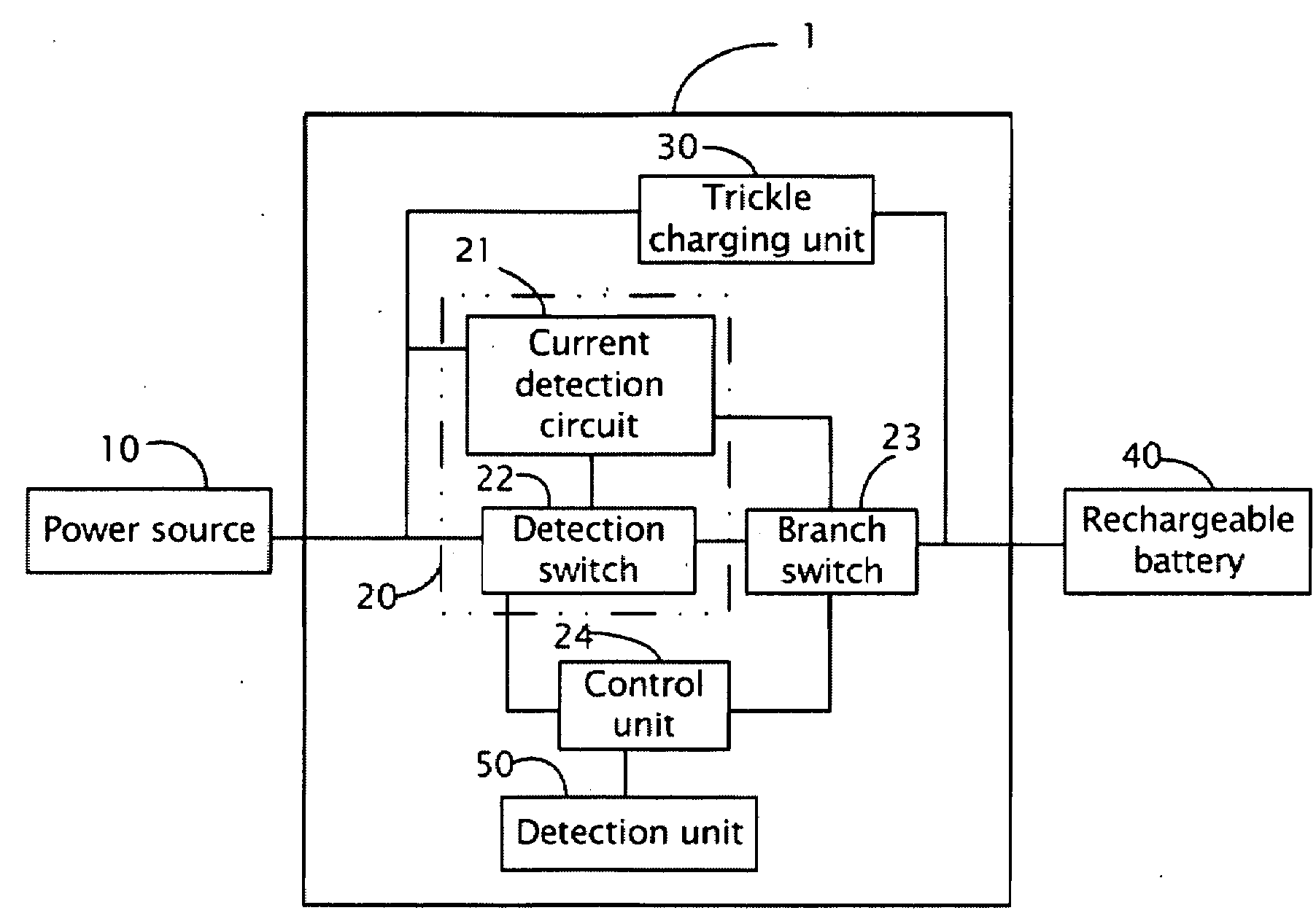
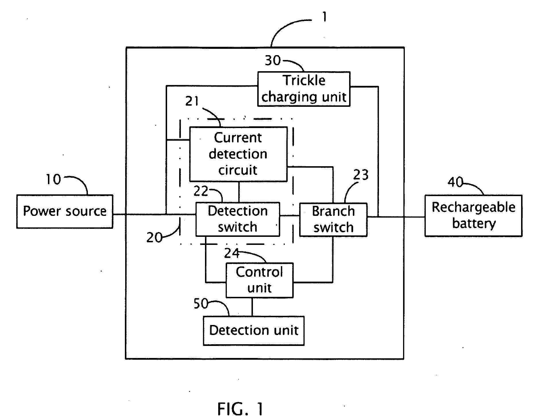
[0010]Referring to FIG. 1, a battery charging control circuit 1 in accordance with an exemplary embodiment, includes a first branch and a second branch which are connected in parallel between a power source 10 and a rechargeable battery 40. The first branch includes a constant-current charging unit 20 and a branch switch 23, the second branch includes a trickle charging unit 30. The constant-current charging unit 20 includes a current detection circuit 21 and a detection switch 22. The battery charging control circuit 1 also includes a control unit 24, which is connected to the constant-current charging unit 20 and the branch switch 23, and includes a detection unit 50, which is connected to the control unit 24. The battery charging control circuit 1 firstly charges the rechargeable battery 40 under control of the constant-current charging unit 20 in a constant-current (cc) mode and then under control of the trickle charging unit 30 in a trickle mode. In the cc mode, the battery cha...


PUM


Abstract

The present disclosure provides a battery charging control circuit. The charging control circuit includes: a constant-current charging unit and a trickle charging unit. The charging control circuit further includes a branch switch, a control unit, and a detection unit. The branch switch is connected between a power source and the rechargeable battery for enabling or disabling the constant-current charging unit. The control unit is between the constant-current charging unit and the branch switch for controlling the branch switch. The detection unit is used to detect a state of the rechargeable battery. If the detection unit detects the state of the rechargeable battery is correspond to a predetermined state, then the control unit controls the branch switch to disable the constant-current charging unit and enable the trickle charging unit.

Description

RELATED APPLICATIONS[0001]This application is related to a co-pending U.S. patent application filed concurrently herewith whose Attorney Docket No. is US 14857 and entitled “BATTERY CHARGING CONTROL CIRCUIT”, which is incorporated herein in its entirety by reference.BACKGROUND[0002]1. Technical Field[0003]The present disclosure relates to battery circuits and, particularly, to a battery charging circuit.[0004]2. General Background[0005]Generally, battery chargers either use a constant current (CC) mode or a constant voltage (CV) mode to charge a battery. However, in either the CC mode or the CV mode, battery charging is terminated once the battery's voltage reaches a peak value (e.g., 4.2 V), which may result in the battery not being fully charged.[0006]Therefore, it is necessary to provide an apparatus and method to overcome the above-identified deficiencies.BRIEF DESCRIPTION OF THE DRAWINGS[0007]The components in the drawings are not necessarily drawn to measuring scale, the empha...

Claims


Application Information

Patent Timeline
IPC IPC(8): H02J7/06H02J7/04
CPCH02J7/0072H02J7/0031H02J7/00714H02J7/007194H02J7/00711
Inventor WANG, HAN-CHECHUNG, SHIN-HONGZHAO, XINOUYANG, HONG-SHENGYOU, RUEY-SHYANG
Owner HONG FU JIN PRECISION IND (SHENZHEN) CO LTD
Why Eureka
Try Eureka