Low pressure paintball guns

a paintball gun and low pressure technology, applied in the field of paintball guns, can solve the problems of airflow becoming more critical and the loss of air can become greater, and achieve the effects of short working stroke, high load-to-stroke ratio, and more controllability

Inactive Publication Date: 2009-10-22
WDP
View PDF12 Cites 10 Cited by
  • Summary
  • Abstract
  • Description
  • Claims
  • Application Information

AI Technical Summary

Benefits of technology

[0012]Some embodiments of the present invention can provide a very high flow poppet valve with assisted closure produced by magnets. Due to their very short working stroke and high load-to-stroke ratio, which is more controllable than a traditional spring, in conjunction with an exhaust port that has a larger surface area than the inlet port, reduction in back pressures and force can be provided, which can normally only be achieved by increasing the valve dwell opening time if sufficient amount of gas flow through the poppet valve is to be achieved.
[0013]The energy for firing the gun is in some embodiments provided by mechanical spring force and its re-cocking energy may be provided by pneumatic force. This cycle can be repeated whenever the gun is fired by means of releasing of a sear that is holding the spring force back. Traditionally blow back guns have to use a high force spring to overcome the force to open the valve but by use of the magnetic poppet valve this force can be greatly reduced allowing a lighter hammer to also be used which reduces the recoil energy. Traditionally blow back gas is very prone to large losses affecting the efficiency of the system. By the addition of an active seal on the hammer, in some embodiments of the invention, friction forces and losses are kept low as the hammer seal only becomes active during its return stroke, or indeed only a part of its return stroke, and does not offer any resistance and losses due to friction on its forward stroke, allowing all the energy from the spring to be imparted to the magnetic exhaust valve.

Problems solved by technology

Some problems with this low pressure operation are that losses can become greater and the airflow becomes more critical as the speed of operation of the gas delivery system is still required to be fast but needs to achieve higher gas flows at lower pressures.

Method used


Image

  • Low pressure paintball guns
  • Low pressure paintball guns
  • Low pressure paintball guns

Examples


Embodiment Construction

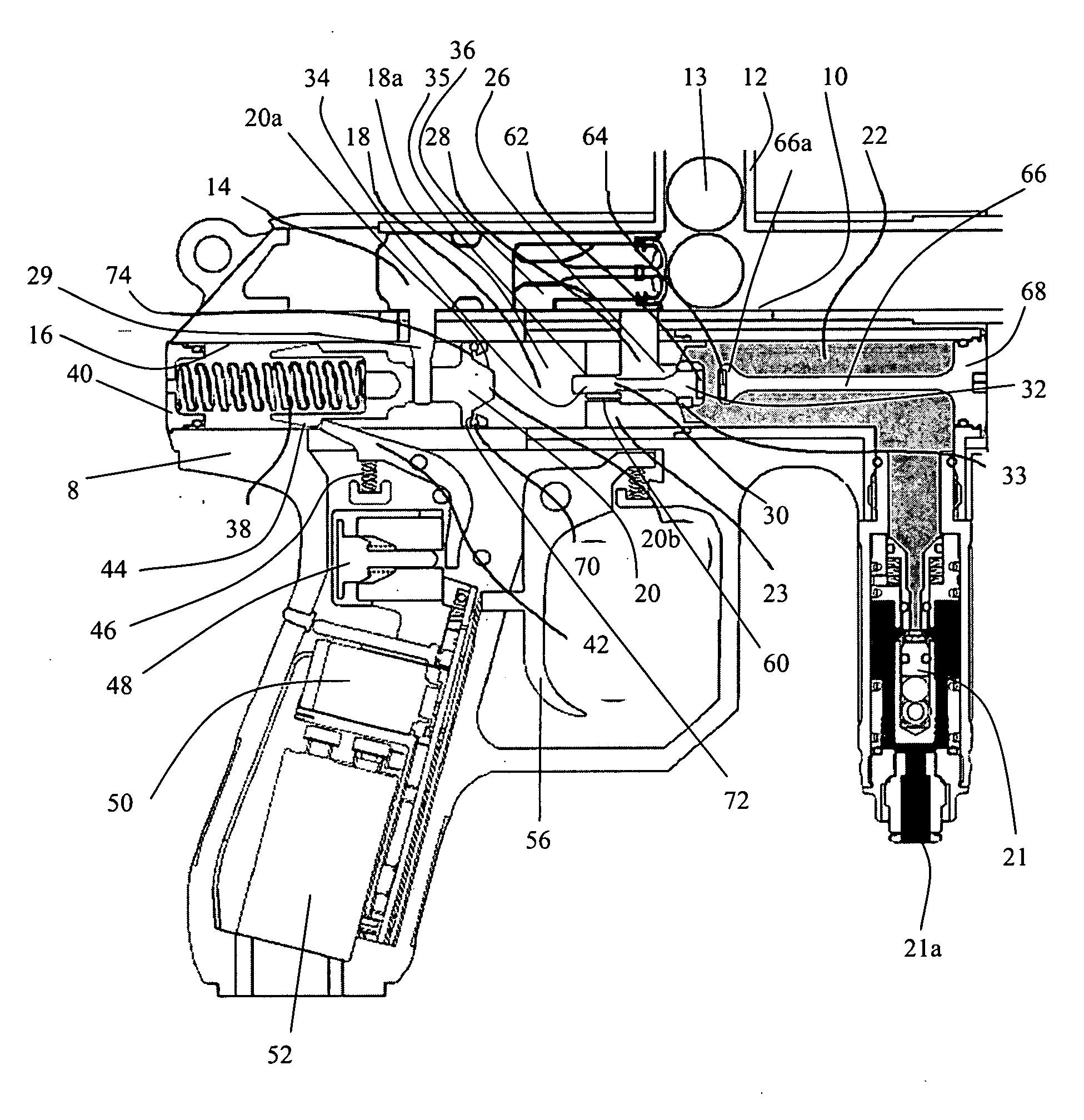
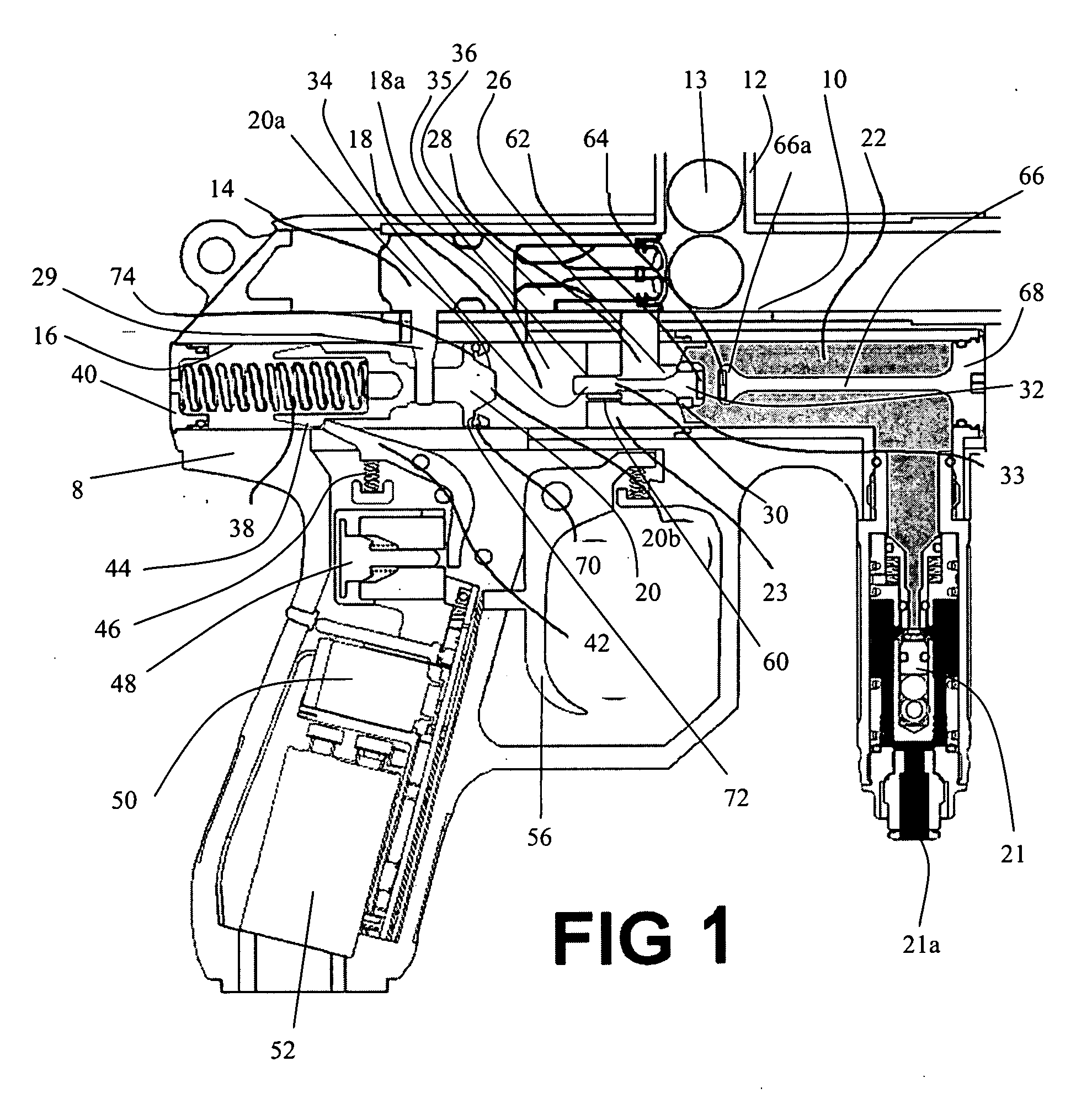
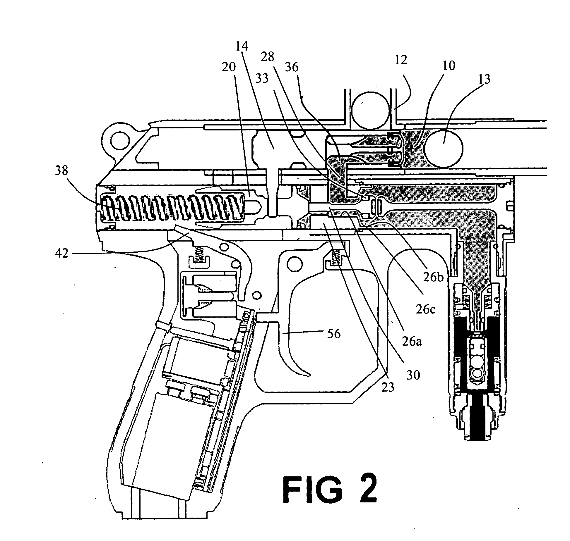
[0019]Referring to FIG. 1, a paintball gun comprises a gun body 8 with a tubular breech 10 formed in it with a paintball feed tube 12 opening into the breech through which paintballs 13 can be fed. A bolt 14 is located in the breech behind the feed tube 12 and is slidable backwards and forwards to load paintballs 13 into the breech 10 and fire them. A further cylindrical cavity 16 is formed in the gun body 8 below the breech 10 the rear part of which forms a hammer chamber 18 in which a hammer 20 is slidably located, and the front part of which forms a gas storage chamber 22. A poppet valve 23, 30 is located in the cavity 16 between the hammer chamber 18 and gas storage chamber 22, and comprises a valve body 23 having a gas inlet 26 and a gas outlet 28 formed in it, and a poppet 30. The gas inlet 26 opens into the gas storage chamber 22 and the gas outlet opens into the breech 10 just behind the paintball feed tube 12. The poppet 30 includes a head 32 which projects into the gas sto...


PUM


Abstract

A paintball gun comprises: a body defining a gas storage chamber for connection to a source of pressurized gas, a breech into which paintballs can be loaded, and a hammer chamber; a bolt slidable in the breech and having a bolt inlet port; a hammer slidable in the hammer chamber and connected to the bolt; and a poppet valve comprising a valve body defining a valve inlet connected to the storage chamber, a valve outlet connected to the breech, and a blow back port connecting the inlet to the hammer chamber, and a valve member slidable in the valve body and movable between an open position, in which it allows gas to flow from the storage chamber through the valve inlet to the valve outlet, and a closed position in which it closes the valve, and a pair of magnets arranged to bias the poppet towards the closed position.

Description

CROSS-REFERENCE TO RELATED PATENT APPLICATIONS[0001]This application claims priority from U.S. Provisional Patent Application No. 61 / 005,461 filed on Dec. 4, 2007 and is incorporated herein by reference in its entirety.FIELD OF THE INVENTION[0002]The present invention relates to paintball guns and in particular to paintball guns arranged to operate at relatively low gas pressure.BACKGROUND OF THE INVENTION[0003]Paintballs for use in paintball guns (also referred to as markers) are constructed from fragile materials that are designed to break on contact with a target.[0004]Paintballs are fired from a marker by gas pressure acting as a propellant and therefore in the construction of a paintball a balance needs to be struck between ensuring that the paintball is strong enough to withstand the initial propellant gas pressure but fragile enough to fracture upon impact. It is therefore desirable to apply as little force as possible to the paintball from the gas pressure, while still impar...

Claims


Application Information

Patent Timeline
Patent Type & Authority Applications(United States)
IPC IPC(8): F41B11/00F41B11/62
CPCF41B11/721
Inventor WALKER, MARK ANDREWRICE, JOHN RONALD
Owner WDP
Why Eureka
Try Eureka