Collapsible container

a container and collapsible technology, applied in the field of collapsible containers, to achieve the effect of improving the stability, rigidity and performance of the container

Inactive Publication Date: 2009-10-22
OTTO INDS OF NORTH AMERICA
View PDF89 Cites 31 Cited by
  • Summary
  • Abstract
  • Description
  • Claims
  • Application Information

AI Technical Summary

Benefits of technology

[0006]The present invention addresses the above needs and achieves other advantages by providing a collapsible container incorporating structures and components for improving the stability, rigidity, and performance of the container.
[0016]The base may further define an interior surface and an exterior surface, and the interior surface of the base may define a contact area that is substantially continuous and configured to contact the items carried by the container, and a base non-contact area. In addition, the base may define at least one opening in the non-contact area of the base configured to provide ventilation for the items. The contact area of the base may be substantially smooth.
[0018]In addition, the base may define an interior portion defined on the interior surface of the base and an exterior portion defined on the exterior surface of the base. The interior portion of the base contact area may be structured to contact the items carried by the container, and the exterior contact portion may be structured to contact items carried by an adjacent container. Furthermore, the interior and exterior portions of the base contact area may be substantially smooth and substantially continuous to reduce the incidence of damage to items carried by the container and to items carried by the adjacent container. In some cases, the interior portion of the base contact area may define a generally concave contour relative to the items carried by the container, and the exterior portion of the base contact area may define a generally convex contour relative to the items carried by the adjacent container. The one or more openings of the base may be defined through the interior and exterior portions of the base non-contact area, and a plurality of stiffening ribs may be defined in the exterior portion of the base non-contact area.
[0021]The interior surface of each of the base and walls may define a contact area configured to contact the items, and the contact areas may be smooth. Alternatively or additionally, the contact areas may be substantially continuous. Furthermore, the exterior surface of the base may define a contact area configured to contact items carried by a second container stacked adjacent to the base, and the contact area of the exterior surface may be smooth.
[0026]In still other embodiments, the container includes a base defining a number of edges, a first pair of opposed walls and a second pair of opposed walls. Each wall has a hinged edge configured to hingedly engage a corresponding edge of the base and an upper edge opposite the hinged edge. Furthermore, each wall of the first wall pair has two opposed first latching edges substantially perpendicular to the hinged edge, and each first latching edge defines a latch tab proximate an interior surface of the respective wall extending in a plane substantially parallel to the plane defined by the interior surface. Similarly, each wall of the second wall pair has two opposed second latching edges substantially perpendicular to the hinged edge, and each wall of the second wall pair defines a tab slot located a distance from the second latching edge substantially equal to the thickness of the adjoining wall of the first wall pair, where the tab slot is configured to receive the latch tab of the adjoining wall of the first wall pair when the container is in the expanded configuration. In this way, an inwardly directed force applied at a mid-portion of the first wall pair proximate the upper edge of the walls of the first wall pair when the container is in the expanded configuration may serve to urge the latch tab into further engagement with the respective tab slot and maintain the container in the expanded configuration.

Problems solved by technology

Applicant has identified a number of deficiencies and problems associated with the manufacture, design, and use of conventional collapsible containers.

Method used


Image

  • Collapsible container
  • Collapsible container
  • Collapsible container

Examples


Embodiment Construction

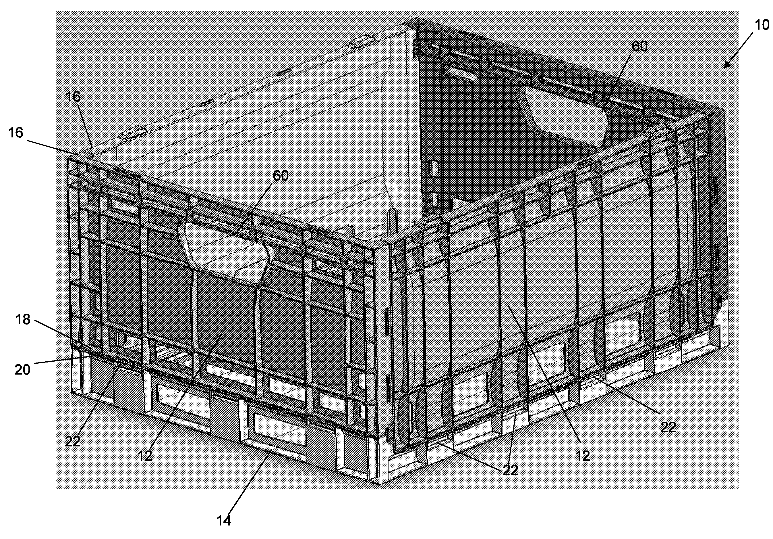
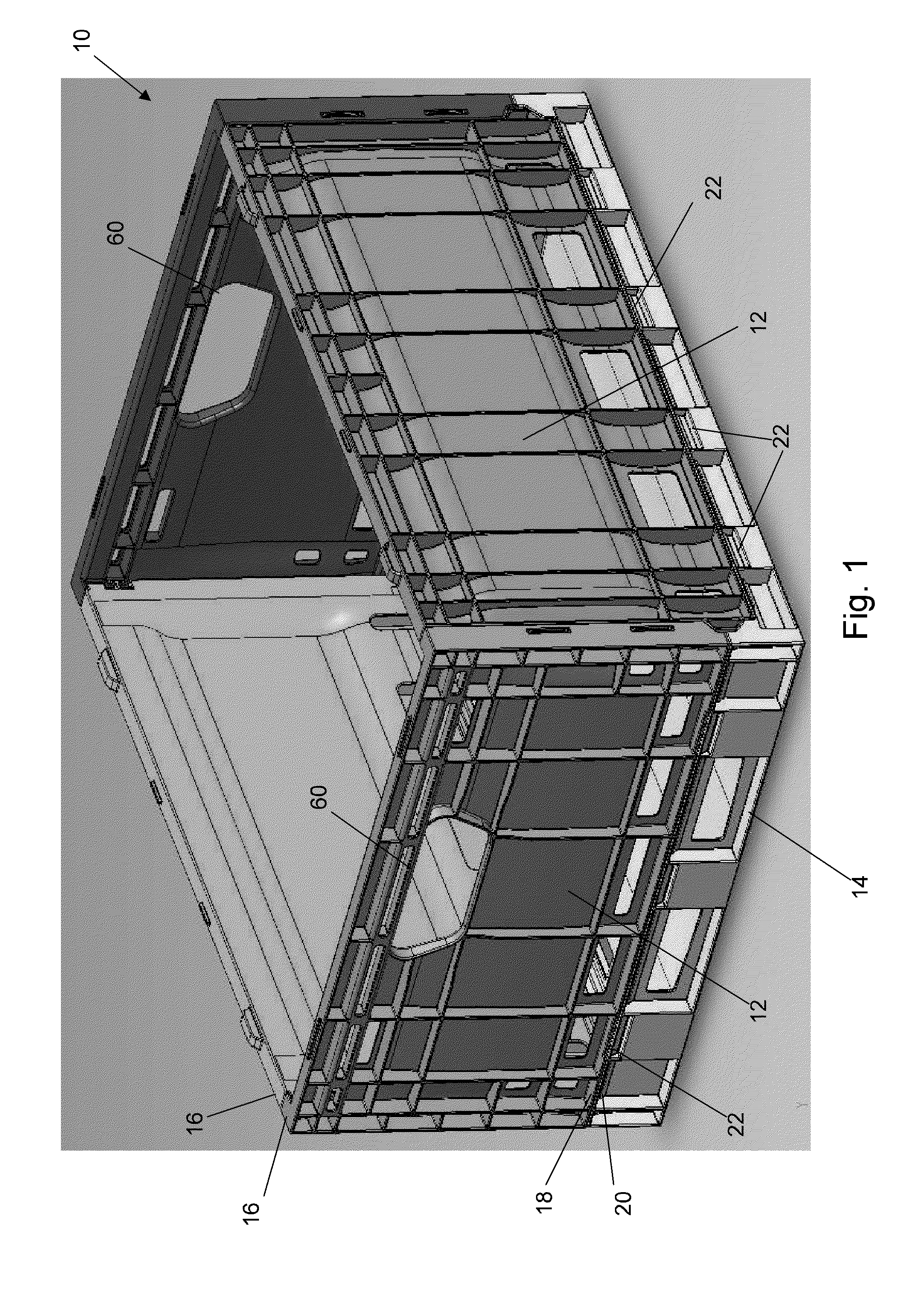
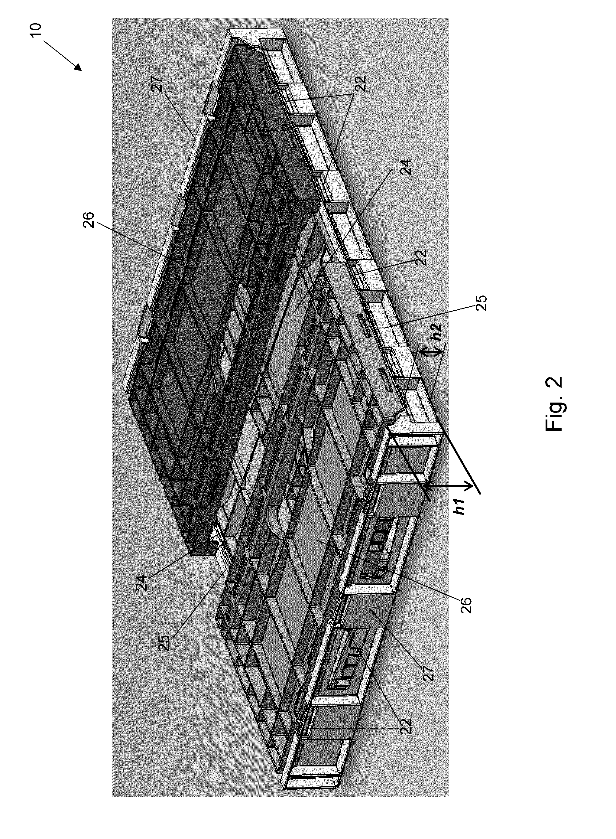
[0064]A number of embodiments of the present invention now will be described more fully hereinafter with reference to the accompanying drawings, in which some, but not all embodiments of the inventions are shown. Indeed, the present invention may be embodied in many different forms and should not be construed as limited to the embodiments set forth herein; rather, these embodiments are provided so that this disclosure will satisfy applicable legal requirements. Like numbers refer to like elements throughout.

[0065]Various embodiments of the invention are directed to a collapsible container incorporating structures and components for improving the stability, rigidity, and performance of the collapsible container. Other embodiments include container structures and components adapted to improve the interaction between the container itself and a stored item. For example, in one embodiment, the collapsible container may be structured to reduce the incidence of bruising and other damage im...


PUM


Abstract

A collapsible container is provided that incorporates various features for improving the stability of the container and for reducing damage to the items carried by the container. The container may include a stabilizing hinge assembly including a stabilizing ledge and a stabilizing hook that securely engage the respective sidewalls to the base of the container to stiffen the container and distribute the loads more evenly. The sidewalls and base of the container may also define contact areas to support the carried items without bruising or damaging the items. Non-contact areas of the container that do not come into contact with the items may include openings that are aligned with other openings in the container and other adjacent containers to provide a consistent flow of air through a number of containers stacked beside one another. The sidewalls may also include various latching features to maintain the container in the expanded configuration.

Description

CROSS-REFERENCE TO RELATED APPLICATIONS[0001]The present application claims the benefit of U.S. Provisional Application No. 61 / 046,851, entitled “Collapsible Container,” filed on Apr. 22, 2008, the contents of which are incorporated herein in their entirety.FIELD OF THE INVENTION[0002]The present invention is directed to assemblies for storing and transporting items, and more particularly to a collapsible container including structural components and features configured to provide increased stability of the container and allow for the storage and transportation of damage-sensitive items, such as bananas and other products.BACKGROUND[0003]Collapsible containers are conventionally used for storing and shipping various items. Collapsible containers can be collapsed (i.e., folded into a relatively flat configuration) for space-efficient storage and can also be expanded (i.e., folded from a collapsed position to a usable position) to define a relatively rigid structure for holding and pr...

Claims


Application Information

Patent Timeline
Patent Type & Authority Applications(United States)
IPC IPC(8): B65D8/14E05D5/10
CPCB65D11/1833B65D11/22Y10T16/557B65D85/34B65D21/0212
Inventor BLANCHARD, WESLEY J.
Owner OTTO INDS OF NORTH AMERICA
Why Eureka
Try Eureka