
Touch-pad cursor control method

Inactive Publication Date: 2009-10-22
E LEAD ELECTRONICS
View PDF2 Cites 66 Cited by
  • Summary
  • Abstract
  • Description
  • Claims
  • Application Information

AI Technical Summary

Benefits of technology

[0011]The first step is to detect if an object is in contact with the touch-pad, the next step is to calculate the location coordinates of the object touching the touch-pad, the next step is to examine if the signal requirement for quick cursor movement exists. If such input exists, the next step includes canceling said input, then moving the cursor around the device's display to the location corresponding to the object touching the touch-pad in absolute coordinate positioning; in this case, the location of the cursor is determined by the location of the object on the touch-pad, when the input object touches a point on the touch-pad, the cursor is subsequently moved to the same relative location on the display screen at once. If the input for quick cursor movement does not exist, the distance and direction of the input motion around the touch-pad corresponds to the location of the cursor on the device's display in relative coordinate positioning. Therefore, the step enables the cursor on the display to be quickly moved near the selection item (ICON) in absolute coordinate positioning; then, slight movements of the cursor in relative coordinate positioning allows for precise aim at the selection item. The next step is to detect if an input button is pressed and the final step is to execute the command of the item selected by the cursor on the display.
[0012]The above method of absolute coordinate positioning contacts coordinate positioning of the screen scale with relevant coordinate positioning of the touch-pad one by one, multiplies each location coordinate of the touch-pad by a specific enlargement ratio to get each correspondent location of the cursor on the display, in addition, the enlargement proportion is determined by respective lengths and widths of the touch-pad and of the display. For example, the upper left corner of the touch-pad is correspondent with the upper left corner of the screen and the lower right side of the touch-pad is correspondent with the lower right side of the screen. The above method in relative coordinate positioning means that the location coordinates of the touch-pad is not directly related to the location coordinates of the screen, in addition, the location and movement of the cursor on the screen is irrelevant to the location of the object on the touch-pad, but is related to the movement of the object on the touch-pad, so that the location and movement of the cursor on the screen is determined by the operation of the object on the touch-pad in both absolute and relative positioning, therefore, the invention is able to achieve the effects of fast cursor moving on the screen and easy icon pointing without the problems and inconvenience caused to a user to repeatedly drag the cursor and rub against the touch-pad.
[0018]The invention enables the location of moving the cursor on the screen to be determined based on the location of moving the object in absolute and relative coordinate positioning, so as to achieve the objective of fast moving the cursor without the problems and inconvenience caused to a user to repeatedly drag the cursor and rub against the touch-pad. A first embodiment of the invention is therefore disclosed herein. The touch-pad activates an input for quick cursor movement and executes relevant commands and calculations in absolute coordinate positioning each time when the object is lifted and re-pointed at the same location on the touch-pad.

Problems solved by technology

The aforementioned arrow keys and joysticks control the direction of cursor movement easily, but lack precise cursor speed control; consequently, such time-consuming operations have not been extensively applied in the field.
In addition, it is more convenient for a user to use his / her finger on the edge of a mouse button to move the cursor around the screen; however, mouse movements require a lot of space, so that such applications are not suitable for a mobile notebook PC or a small electronic device.
Nowadays, touch panels have been widely applied in various small electronic devices, but there are several disadvantages to using a finger or a touch pen.
For example, the palm of hand usually hinders a user from screen views, the finger touch easily stains the screen, etc.
Most modern notebook PCs have been equipped with touch-pads as standard pointing device applications, less space is required for operations and users are used to such arrangement, though existing touch-pad operations may not be as smooth as the use of a mouse.
If the finger movements are scaled aggressively, the cursor moves further without repeated finger motion; however, it is harder for a user to aim at a target location and move his / her finger around the screen accurately.
This method slightly reduces the above problem of using a device with a touch-pad; nevertheless, such a method is unable to satisfy most users, who find frequent finger motion on the touch-pad inconvenient.
However, the prior art of the U.S. Pat. No. 5,327,161 still has a practical problem of precisely pointing the cursor at an object on the screen due to sensitivity.
This method slightly reduces the above problem of using a device with a touch-pad; however, such a method is unable to satisfy most users, who find frequent finger motion on the touch-pad inconvenient.
Consequently, many users of notebook PCs with pre-installed touch-pad devices still use a supplementary mouse; since an additional portable mouse is required, the touch-pad design is superfluous.

Method used


Image

  • Touch-pad cursor control method
  • Touch-pad cursor control method
  • Touch-pad cursor control method

Examples


Embodiment Construction

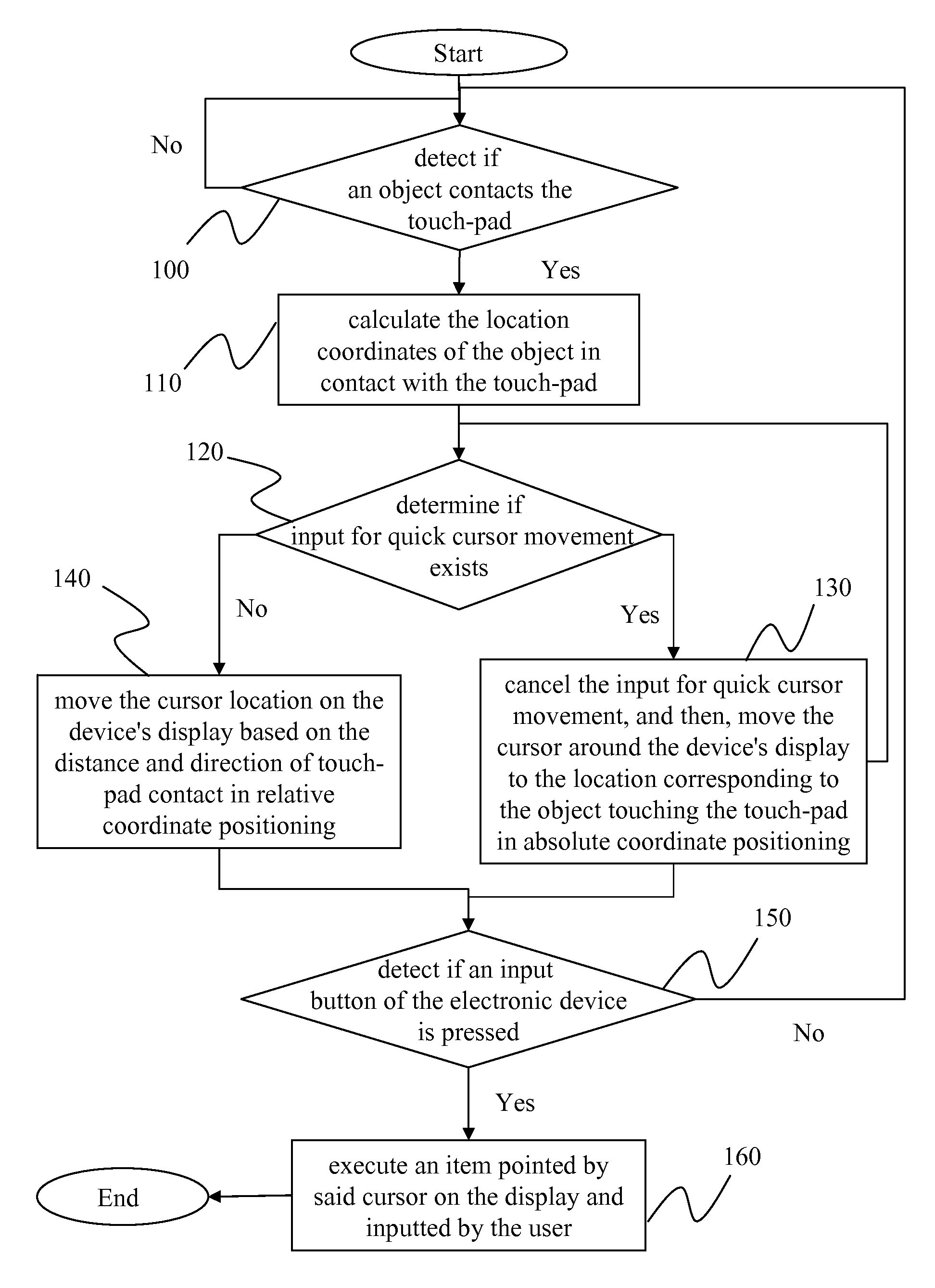
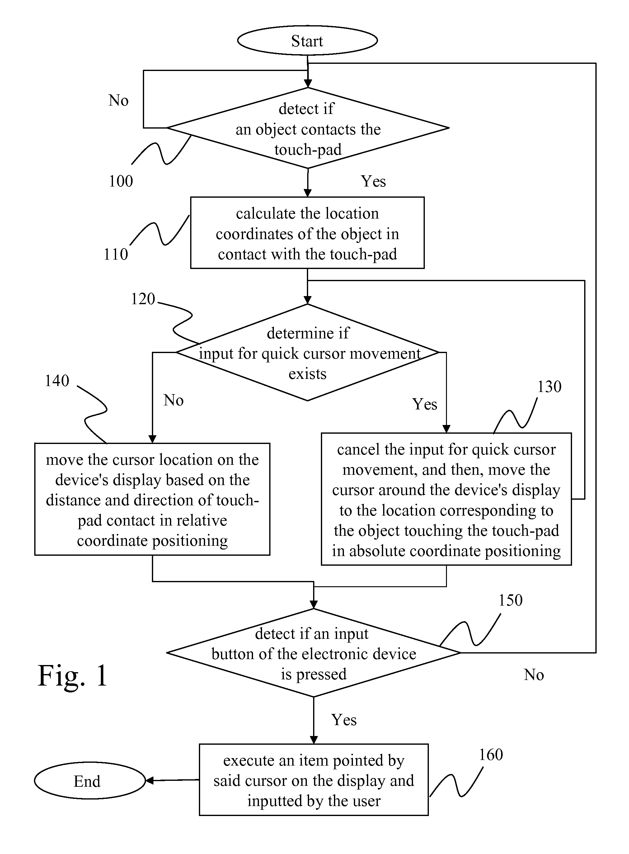
[0030]The invention discloses a touch-pad cursor control method herein. Prior to introduction to the invention's method, the design and concept of the invention is described as follows. Generally, a user uses his / her finger or a touch pen to point on a touch panel product, the cursor is moved to relevant location on the display; whereas when a user uses his / her finger to move around the touch-pad, the cursor is then moved on the display. The invention is therefore applies the advantages of both touch panel screen and touch-pad to disclose a convenient method for users.

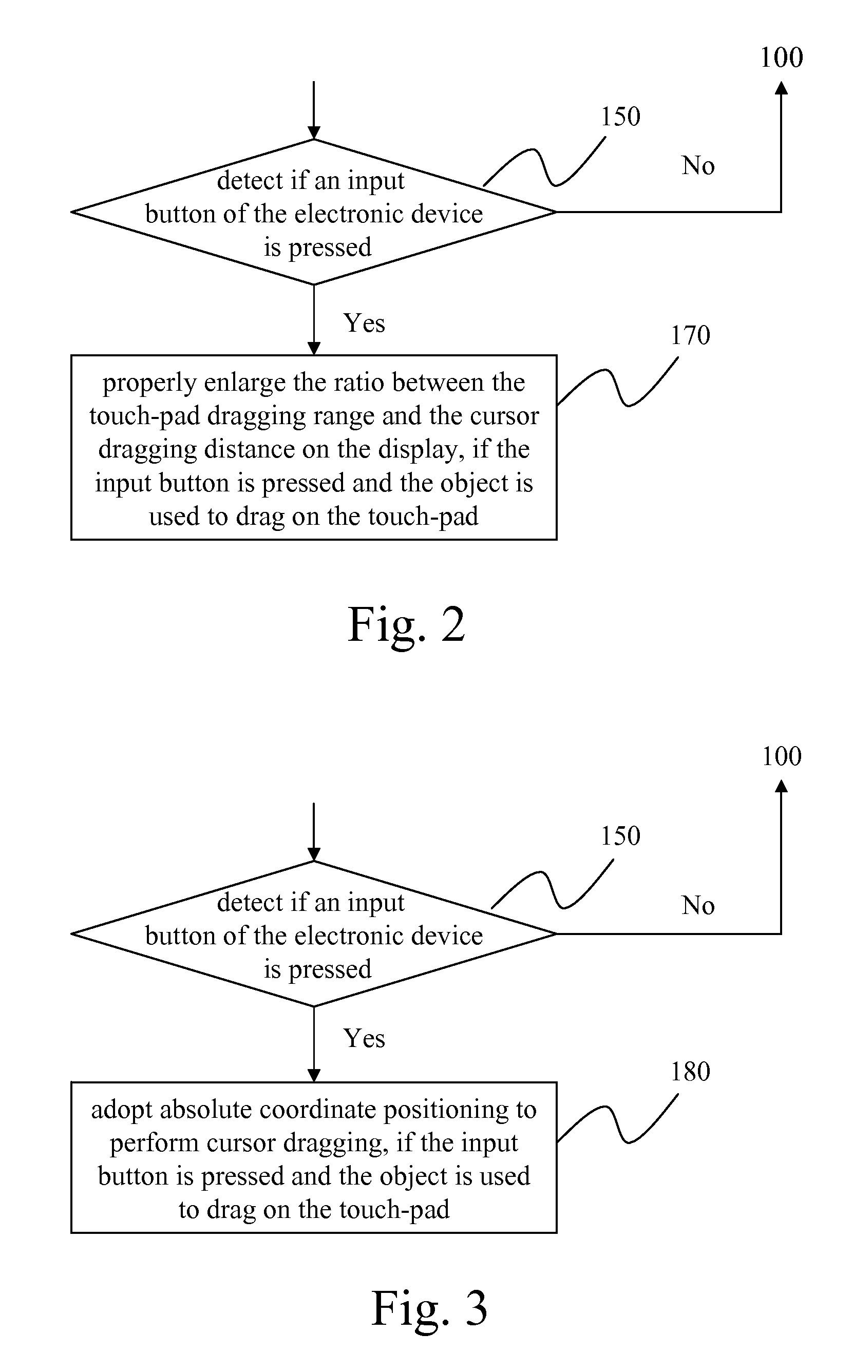
[0031]FIG. 1 is a flow chart of the invention's touch-pad cursor control method. The invention's touch pad is placed in an electronic device, (here, a notebook computer, but application is not limited to notebook computers, any kind of electronic device that allows data input could use it). The control method involves the following steps. The first step is to detect if an object is in contact with the touch-pad (Step 1...


PUM


Abstract

A touch-pad cursor control method is discussed. The touch-pad invention is placed in an electronic device and its control method is comprised of steps detecting if an object contacts the touch-pad; detecting the location of the object contacting the touch-pad; examining if an input for quick cursor movement exists, if YES, dragging the cursor on the device's display to the corresponding location of the object on the touch-pad in absolute coordinate positioning, if NOT, mapping the moving distance and direction of the object on the touch-pad to the position of the cursor on the device's display in relative coordinate positioning; detecting if an input button of the electronic device is pressed; and finally, executing a command based on an item pointed by said cursor on the display. By basing cursor movement on touch-pad input in both absolute and relative coordinate positioning methods, the invention determines cursor location, achieving a fast moving cursor effect

Description

FIELD OF THE INVENTION[0001]The present invention relates to a touch-pad cursor control method, specifically a method of controlling a touch-pad cursor that achieves faster cursor movement.BACKGROUND OF THE INVENTION[0002]Generally, human-computer interaction is composed of a character input device and directional control device; while the character input device generally includes keyboards or hand writing devices, the directional control device is for controlling cursor movements. Such devices include mouses, joysticks, arrow keys, touch panels, touch-pads, etc. The aforementioned arrow keys and joysticks control the direction of cursor movement easily, but lack precise cursor speed control; consequently, such time-consuming operations have not been extensively applied in the field. In addition, it is more convenient for a user to use his / her finger on the edge of a mouse button to move the cursor around the screen; however, mouse movements require a lot of space, so that such appl...

Claims


Application Information

Patent Timeline
IPC IPC(8): G06F3/041G06F3/0481
CPCG06F3/0488G06F3/03547
Inventor CHEN, STEPHEN
Owner E LEAD ELECTRONICS
Learn More