
Liquid crystal display device

Inactive Publication Date: 2009-10-22
LG DISPLAY CO LTD
View PDF11 Cites 13 Cited by
  • Summary
  • Abstract
  • Description
  • Claims
  • Application Information

AI Technical Summary

Benefits of technology

[0025]Therefore, it is an object of the present invention to provide a liquid crystal display (LCD) device having a protection member capable of protecting an LC panel from an external impact, and capable of enhancing an outdoor visibility.
[0028]To achieve these and other advantages and in accordance with the purpose of the present invention, as embodied and broadly described herein, there is provided a liquid crystal display (LCD) device, comprising: an LC panel for displaying images; a backlight unit disposed below the LC panel, and providing light; a protection member provided on the LC panel, and consisting of a tempered substrate for protecting the LC panel from an external impact, and an anti-reflect layer formed on the tempered substrate and reducing a reflectivity of external light; and an adhesive layer formed of a material having a similar refractivity to the LC panel and the tempered substrate of the protection member, for adhering the protection member onto the LC panel by being interposed therebetween.

Problems solved by technology

The LCD device having a protection member may have a light leakage phenomenon that light provided from a backlight disposed below the LC panel at an edge of the protection member leaks.

Method used


Image

  • Liquid crystal display device
  • Liquid crystal display device
  • Liquid crystal display device

Examples


first embodiment

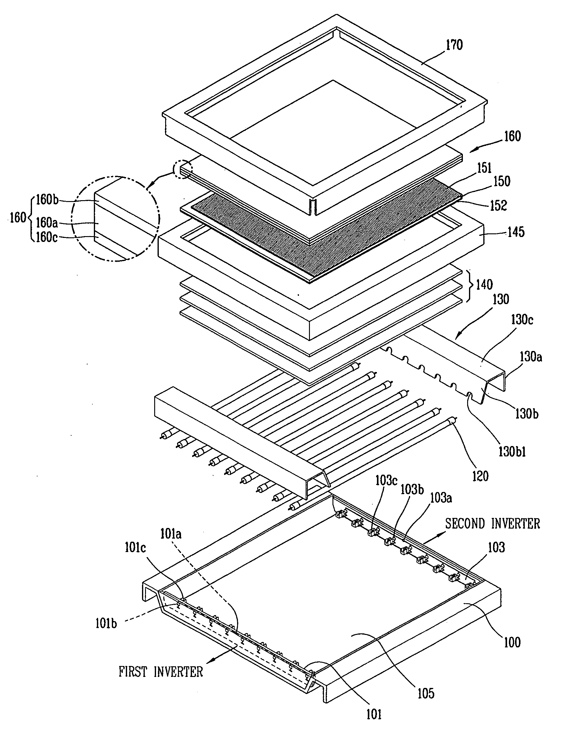
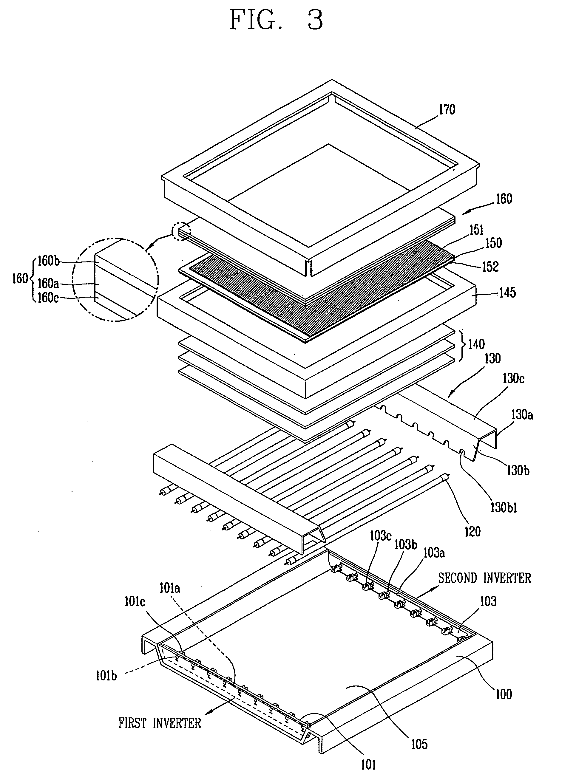
[0044]FIG. 3 is an exploded perspective view of an LCD device according to the present invention, FIG. 4 is a partial sectional view showing a coupled state of the LCD device of FIG. 3, and FIG. 5 is a view showing a refractivity of a protection member of FIGS. 3 and 4.

[0045]Referring to FIGS. 3 to 5, the a liquid crystal display (LCD) device according to a first embodiment of the present invention comprises: a backlight unit (not shown) for providing light by receiving a voltage from outside; an LC panel 150 disposed above the backlight unit, and displaying images; and a protection member 160 consisting of a tempered substrate 160a formed on the LC panel 150 and protecting the LC panel 150 from an external impact, and an anti-reflect layer 160b formed on the tempered substrate 160a and reducing a reflectivity of external light, wherein the protection member 160 includes an adhesive layer 160c formed of a material having a similar refractivity to the tempered substrate 160a of the p...

second embodiment

[0086]In order to solve this problem, an LCD device according to the present invention will be explained.

[0087]FIG. 7 is a partial sectional view of an LCD device according to a second embodiment of the present invention in contrast to FIG. 4, and FIG. 8 is a perspective view of a protection member of FIG. 7.

[0088]Referring to FIGS. 7 and 8, the a liquid crystal display (LCD) device according to a second embodiment of the present invention comprises: a backlight unit (not shown) for providing light by receiving a voltage from outside; an LC panel 250 disposed above the backlight unit, and displaying images; and a protection member 260 consisting of a tempered substrate 260a formed on the LC panel 250 and protecting the LC panel 250 from an external impact, and an anti-reflect layer 260b formed on the tempered substrate 260a and reducing a reflectivity of external light, wherein the protection member 260 includes an adhesive layer 260c formed of a material having a similar refractivi...


PUM


Abstract

Disclosed is a liquid crystal display (LCD) device having a protection member capable of enhancing reliability against an external impact, and an outdoor visibility against an external light. The LCD device comprises: an LC panel for displaying images; a backlight unit disposed below the LC panel, and providing light; a protection member provided on the LC panel, and consisting of a tempered substrate for protecting the LC panel from an external impact, and an anti-reflect layer formed on the tempered substrate and reducing a reflectivity of external light; and an adhesive layer formed of a material having a similar refractivity to the LC panel and the tempered substrate of the protection member, for adhering the protection member onto the LC panel by being interposed therebetween.

Description

RELATED APPLICATION[0001]The present invention relates to subject matter contained in priority Korean Application No. 10-2008-0036679, filed on Apr. 21, 2008 and 10-2008-0081337, filed on Aug. 20, 2008, which are herein expressly incorporated by reference in their entirety.BACKGROUND OF THE INVENTION[0002]1. Field of the Invention[0003]The present invention relates to a liquid crystal display (LCD) device, and more particularly, to an LCD device having a protection member capable of enhancing reliability against an external impact and preventing outdoor visibility from being lowered due to an external light.[0004]2. Description of the Background Art[0005]Generally, a cathode ray tube (CRT), one of most widely used display devices is mainly applied to a television, monitors of meters, information terminal devices, etc. However, the CRT may cause problems in implementing a compact and light-weighted configuration of electronic devices due to its weight and size.[0006]In order to repla...

Claims


Application Information

Patent Timeline
IPC IPC(8): G02F1/1333
CPCG02F1/133502G02F1/133512G02F2202/28G02F2201/50G02F2201/38G02B5/30G02F1/1335
Inventor KANG, WON-SEOKLEE, JONG-BEOM
Owner LG DISPLAY CO LTD
Learn More