Joint assembly with centering flange

a technology of centering flange and joint assembly, which is applied in the direction of couplings, manufacturing tools, mechanical devices, etc., can solve the problems of requiring precision fit and easy binding, and achieve the effect of minimizing the force necessary and increasing the tolerance between the centering flange and the second rotating par

Inactive Publication Date: 2009-10-22
STEERING SOLUTIONS IP HLDG
View PDF24 Cites 4 Cited by
  • Summary
  • Abstract
  • Description
  • Claims
  • Application Information

AI Technical Summary

Benefits of technology

[0008]The present invention provides a joint assembly for operatively coupling first and second rotating parts. The first rotating part includes a CV joint that has a first CV joint member and a second CV joint member, the second CV joint member adapted for mounting to the second rotating part. At least one torque-transmitting element is disposed between the first and second CV joint members for operatively coupling the first and second CV joint members. The second CV joint member includes a centering flange disposed about an axis and having a first length for mounting to the second rotating part. The centering flange has a contact section configured for being in a substantially interference fit with the second rotating part when mounting the centering flange to the second rotating part. The contact section has a second length substantially smaller than the first length of the centering flange such that the substantially interference fit between the centering flange and the second rotating part provides alignment between the centering flange and the second rotating part while minimizing forces necessary to mount the centering flange to the second rotating part.
[0009]By making the length of the contact section substantially smaller than the overall length of the centering flange, the substantially interference fit requires displacement of less material than the prior art centering flange shown in FIG. 1 with the same outer dimensions. As a result, tolerances between the centering flange and the second rotating part can be increased. In other words, variations in dimensions of the centering flange of the present invention can be higher than the prior art centering flange since the contact section of the centering flange of the present invention is much smaller than that of the prior art centering flange.

Problems solved by technology

Furthermore, this prior art centering flange, which is cylindrical so as to present a straight pilot, requires a precision fit and is susceptible to binding.

Method used


Image

  • Joint assembly with centering flange
  • Joint assembly with centering flange
  • Joint assembly with centering flange

Examples


Embodiment Construction

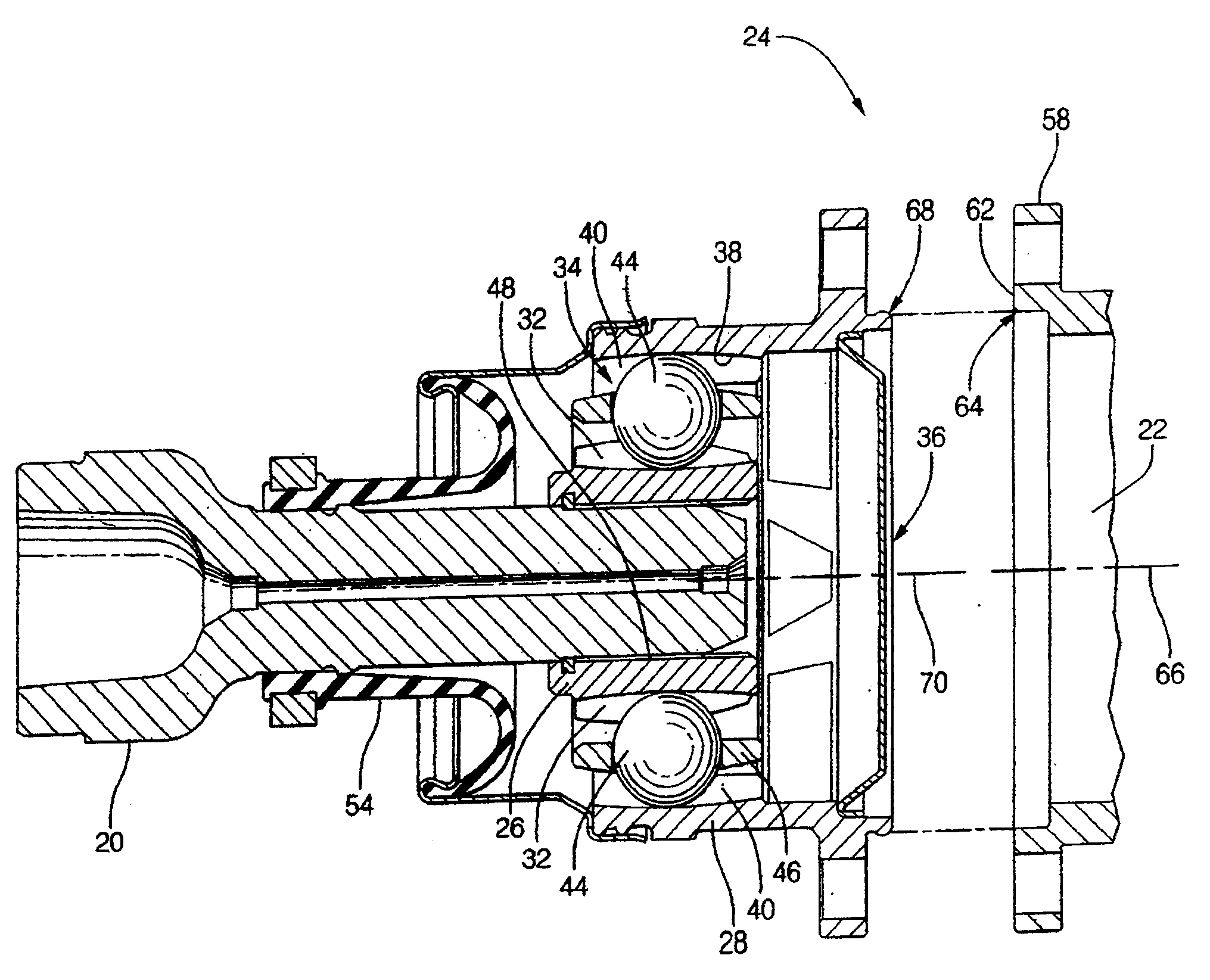
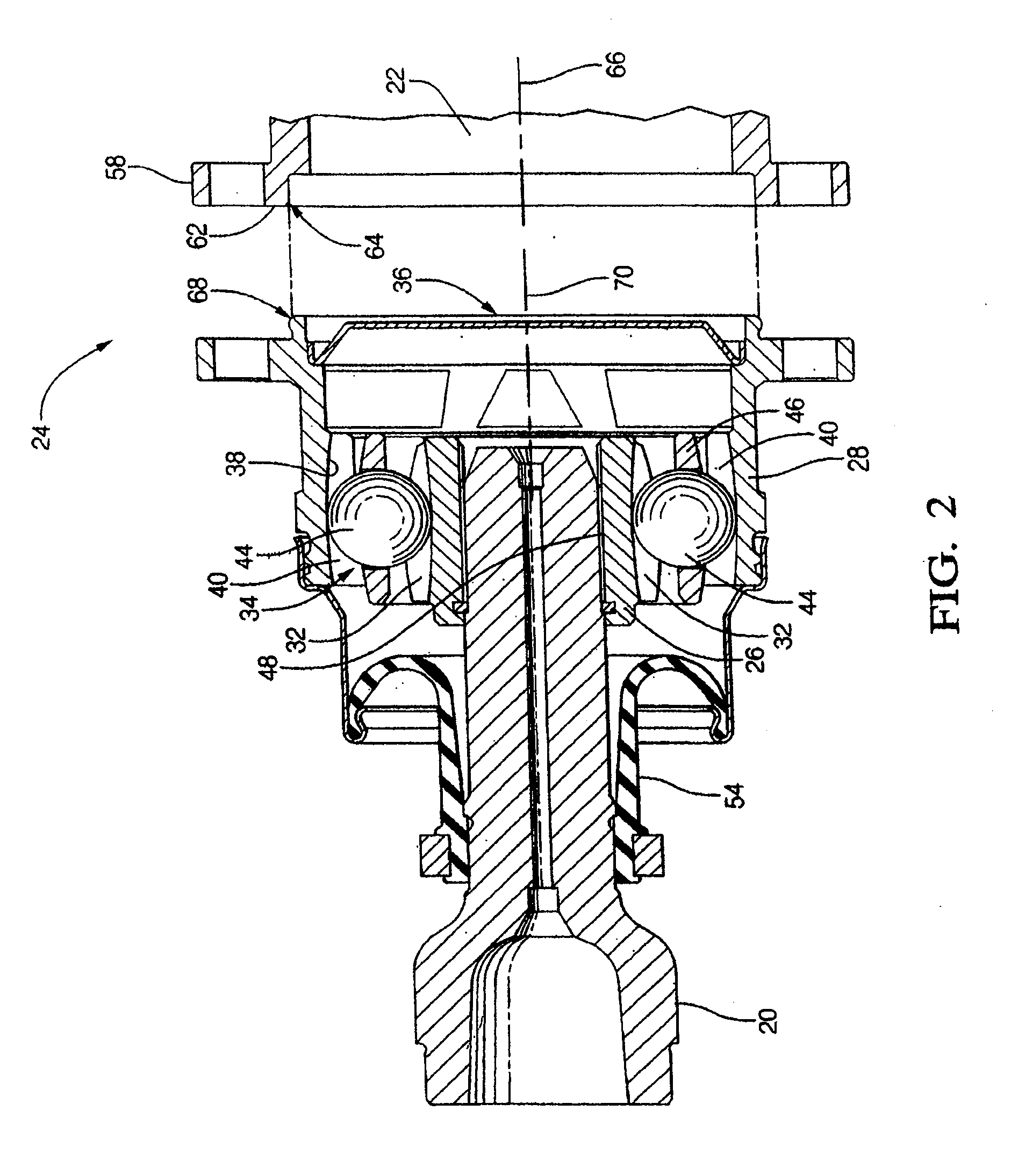
[0017]Referring to the Figures, wherein like numerals indicate like or corresponding parts throughout the several views, a joint assembly for coupling first 20 and second 22 rotating parts is shown generally at 24. In one embodiment, the first rotating part 20 is described as including a constant velocity or CV joint. However, the joint assembly 24 may be any joint assembly capable of operatively coupling parts for rotation, while allowing the parts to deviate from perfect axial alignment with one another.

[0018]Referring to FIGS. 2-3, the first rotating part 20 includes a CV joint having a first CV joint member 26, known as an inner race in some embodiments and a second CV joint member 28, known as an outer race in some embodiments, that is mounted to the second rotating part 22, thereby forming joint assembly 24. As is typical of known CV joints, the first CV joint member 26 is formed with an outer curved surface 30 (see FIG. 3) in which a plurality of first ball grooves 32 are for...


PUM


Abstract

A joint assembly for coupling first and second rotating parts, including a first joint member for mounting to the first rotating part, a second joint member including a centering flange having a first length disposed about an axis for mounting to the second rotating part, and at least one torque-transmitting element disposed between the first and second joint members for operatively coupling the first and second joint members. The centering flange has a contact section configured for being in a substantially interference fit with the second rotating part when mounting the centering flange to the second rotating part. The contact section has a second length substantially smaller than the first length of the centering flange such that the substantially interference fit between the centering flange and the second rotating part provides alignment between the centering flange and the second rotating part while minimizing forces necessary to mount the centering flange to the second rotating part.

Description

CROSS REFERENCE TO RELATED APPLICATION[0001]This application is a continuation of co-pending U.S. patent application Ser. No. 11 / 355,365, filed Feb. 16, 2006, which claims priority to and all the benefits of, and incorporates by reference, U.S. provisional patent application Ser. No. 60 / 654,323, filed Feb. 18, 2005.BACKGROUND OF THE INVENTION[0002]1. Field of the Invention[0003]The present invention relates generally to joint assemblies for operatively coupling rotating parts. More specifically, the present invention relates to joint assemblies comprising multiple joint members with one of the joint members having a centering flange for mounting to one of the rotating parts.[0004]2. Description of Related Art[0005]Joint assemblies for operatively coupling first and second rotating parts are well known in the art. One particularly well known joint assembly is that formed between one end of what is referred to as a constant velocity or CV joint that is included in the first rotating p...

Claims


Application Information

Patent Timeline
Patent Type & Authority Applications(United States)
IPC IPC(8): F16C11/06
CPCF16D1/076Y10T403/64Y10T403/32204Y10T403/645Y10T16/53235F16D2003/22326F16B2200/50F16B2200/506
Inventor KOZLOWSKI, KEITH A.MOLINAR, SERGIO
Owner STEERING SOLUTIONS IP HLDG
Why Eureka
Try Eureka