Clutch control system

a control system and clutch technology, applied in the direction of clutches, engine controllers, mechanical devices, etc., can solve the problems of not seeking to integrate the torque limiting clutch and control system with the system, rendering such systems substantially inflexible to adapt to varying operational conditions, and not seeing the wisdom

Active Publication Date: 2009-10-22
PT TECH LLC
View PDF14 Cites 24 Cited by
  • Summary
  • Abstract
  • Description
  • Claims
  • Application Information

AI Technical Summary

Benefits of technology

[0007]In light of the foregoing, it is a first aspect of the invention to provide a torque limiting clutch control system that is extensively adaptive in nature, accommodat...

Problems solved by technology

Indeed, prior art systems have not been given to change at all once the system is configured, rendering such systems substantially inflexible to adapting to varying operational conditions.
Further, the prior art has not sought to integrate the torque limiting clutch and control system with the system as a whole, such that the torque setting of the clutch may be set automatically to match the torque capability of the engine or the drive system.
Indeed, the prior art has not seen the wisdom of interconnecting the torque limiting clutch and its control system to the SAE J1939 CAN Bus Network of the equipment, so that the clutch and its control system are an integral part thereof and can be adjusted as a...

Method used


Image

  • Clutch control system
  • Clutch control system
  • Clutch control system

Examples


Embodiment Construction

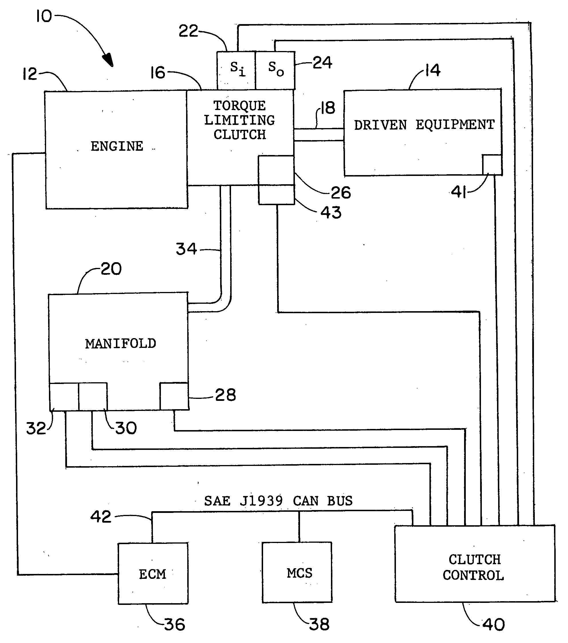
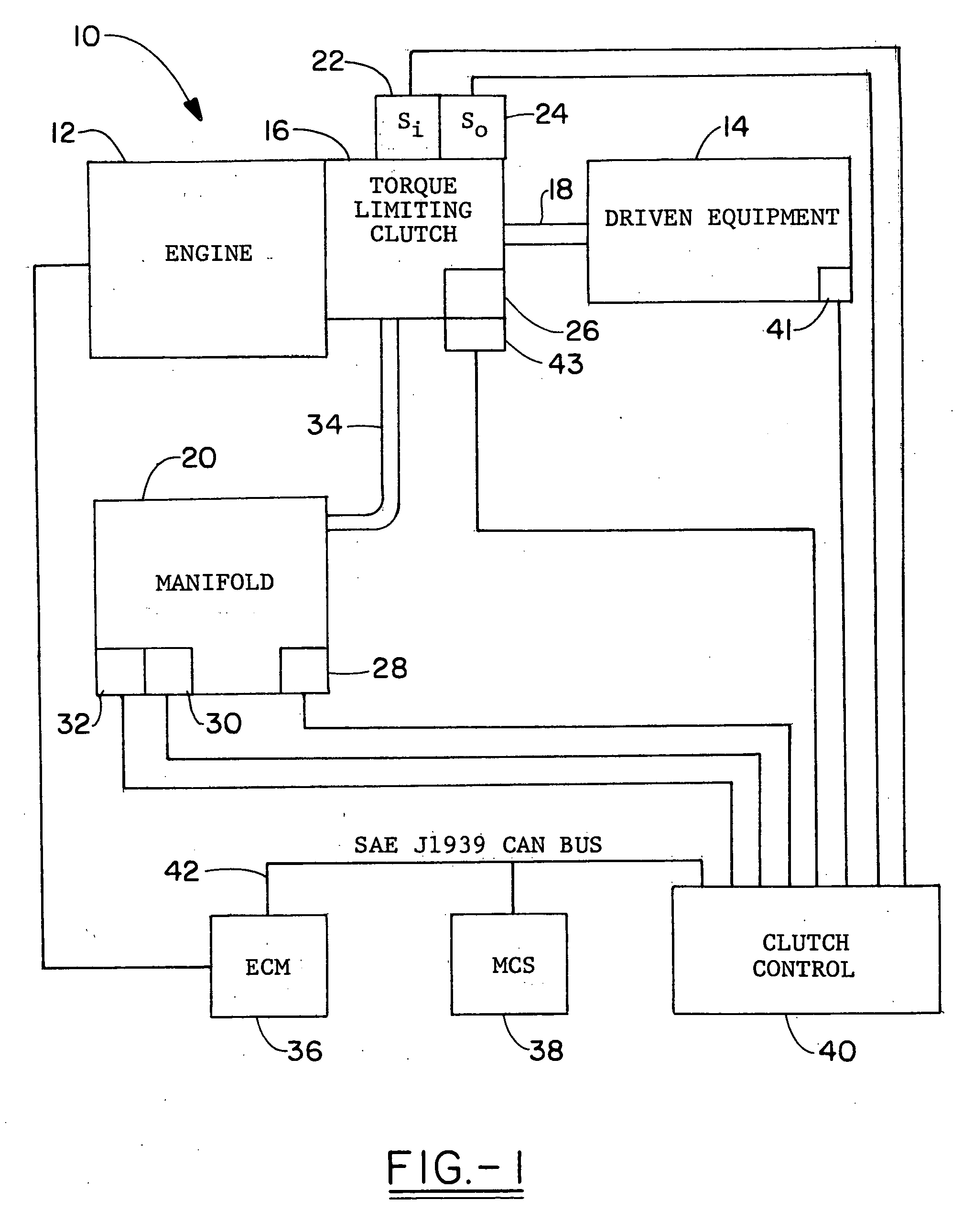
[0024]Referring now to the drawings and more particularly FIG. 1, it can be seen that a torque limiting clutch control system according to the invention is designated generally by the numeral 10. The system 10 includes an appropriate engine 12, such as a diesel engine or the like, interconnected with a piece of driven equipment 14, which may be of any of various types. Typically, the driven equipment 14 may be a chipper, grinder, rock crusher, auger, or any of numerous types of processing equipment. A hydraulic torque limiting clutch 16 is connected to the engine 12 on one side thereof and to the driven equipment 14 through an output shaft 18, on the other side thereof. Of course, people skilled in the art will understand that an appropriate input shaft may be interposed between the engine 12 and torque limiting clutch 16 rather than employing the direct connection as shown in FIG. 1.

[0025]A manifold 20 is employed in direct communication with the torque limiting clutch 16, as shown...


PUM


Abstract

A clutch control system is interposed between an engine and a piece of driven equipment. The clutch control system includes a clutch assembly with input and output speed sensors for providing signals corresponding to the shaft rotational speeds of the engine and the driven equipment, respectively. A pressure sensor is connected to the clutch assembly and provides an output signal corresponding to clutch pressure. A temperature sensor is also associated with the clutch assembly and provides a temperature signal corresponding to the operating temperature of the clutch assembly. Transducers of various types are also employed to sense operating conditions such as shock loads or the like. Also included is a machine control system connected to the driven equipment and an engine control module connected to the engine, both of which are interconnected through an SAE J1939 CAN to the clutch control unit. These signals are passed to a clutch control unit that employs the signals to assess the operating conditions of the system and accordingly adjust the clutch pressure through a pressure control valve. A vast array of operating data is available from the system and is employed by the clutch control unit to ensure optimum operation, by tailoring the clutch pressure to the engine and driven equipment, thus minimizing clutch slippage and avoiding or instantaneously correcting shock load situations.

Description

TECHNICAL FIELD[0001]The invention herein resides in the art of power transmission devices and, more particularly, to torque limiting clutches and control systems associated therewith. Specifically, the invention relates to an adaptive clutch control system that serves to optimize the operational efficiency of the equipment with which the torque limiting clutch and control system are employed, while continuing to maintain and optimize the protection provided that equipment and associated power source.BACKGROUND ART[0002]The utilization of torque limiting clutches to protect interengaged engines and driven equipment is now well known. However, such torque limiting clutches and associated control systems have typically been of a nature as to be specifically tailored to both the engine and the driven equipment and without adaptation to change parameters during operation as a consequence of operational characteristics actually sensed during operation. Indeed, prior art systems have not ...

Claims


Application Information

Patent Timeline
IPC IPC(8): B60W10/02
CPCF16D48/06F16D2500/30404F16D2500/30406Y10T477/753F16D2500/50296F16D2500/70424F16D2500/3166
Inventor HERCHICK, ROBERT E.HEIDENRCICH, DAVID C.OLSON, ERIK L.GUINTER, JOSEPH W.PETERMAN, DAVID A.GOUKER, ARTHUR F.CLAPP, TIMOTHY A.
Owner PT TECH LLC
Why Eureka
Try Eureka