Staged release of ivc filter legs

a technology of vena cava and filter legs, which is applied in the field of vena cava filters, can solve the problems of filter dislocation from its intended placement position, asymmetrical deployment of filter within the body,

Inactive Publication Date: 2009-10-22
LIFESCREEN SCI
View PDF22 Cites 30 Cited by
  • Summary
  • Abstract
  • Description
  • Claims
  • Application Information

AI Technical Summary

Benefits of technology

[0008]In certain embodiments, the catheter may further include one or more grooves or indentations formed along the inner surface of the distal section. The grooves or indentations are radially aligned with each of the notches or slits, and are configured to slidably receive the hook region on each filter leg. In use, the grooves or indentations ensure proper radial alignment of the filter legs within the inner lumen, and prevent leg crossing as the filter legs eject from the catheter.

Problems solved by technology

Since many introducer catheters deploy the filter legs simultaneously in a single step, the spring force resulting from the deployment of the filter legs within the vessel may cause the filter to displace from its intended placement position.
In some cases, the hooks on the ends of the filter legs may also interfere with each other, causing the filter to asymmetrically deploy within the body.

Method used


Image

  • Staged release of ivc filter legs
  • Staged release of ivc filter legs
  • Staged release of ivc filter legs

Examples


Embodiment Construction

[0015]The following description should be read with reference to the drawings, in which like elements in different drawings are numbered in like fashion. The drawings, which are not necessarily to scale, depict selected embodiments and are not intended to limit the scope of the invention. Although examples of construction, dimensions, and materials are illustrated for the various elements, those skilled in the art will recognize that many of the examples provided have suitable alternatives that may be utilized.

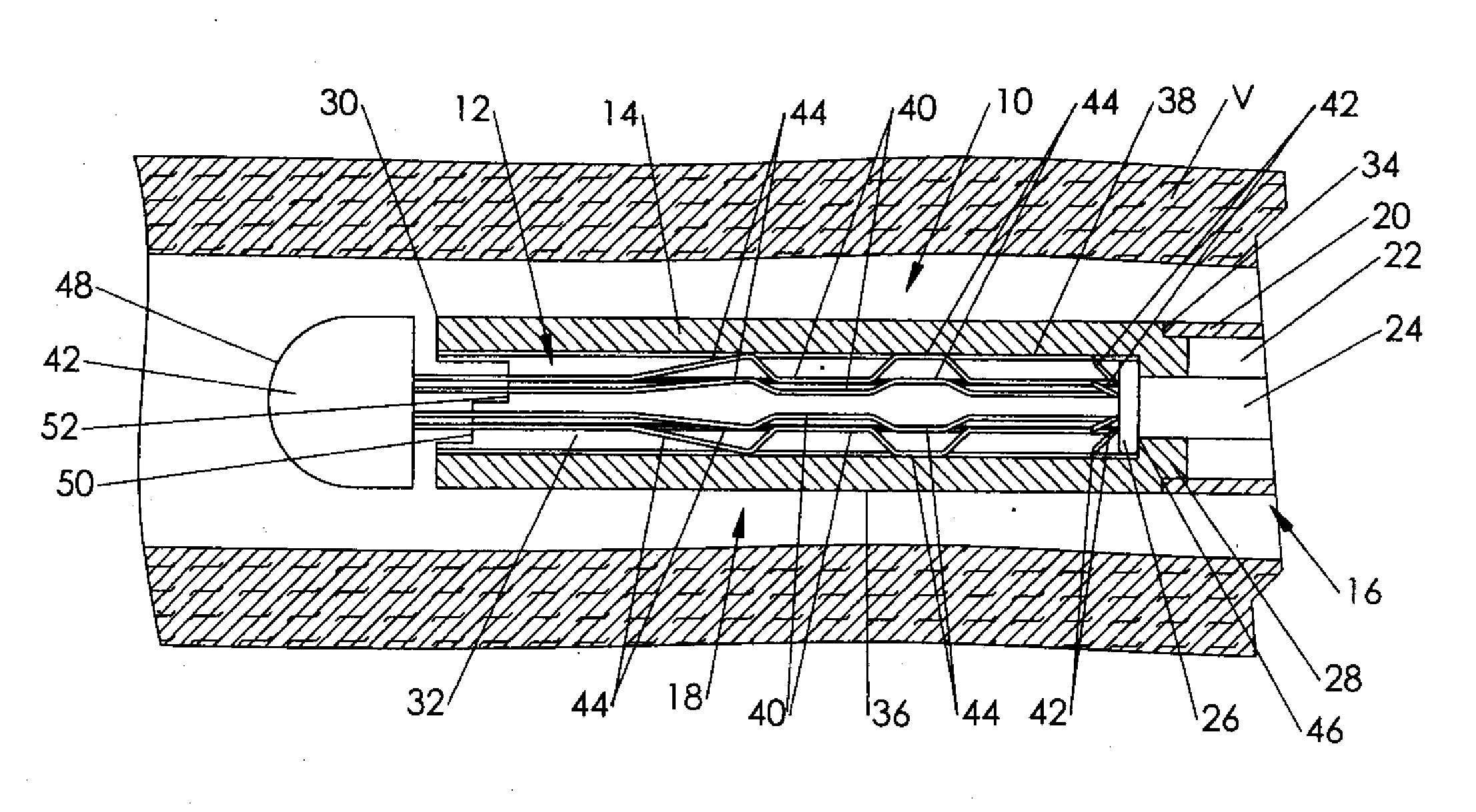
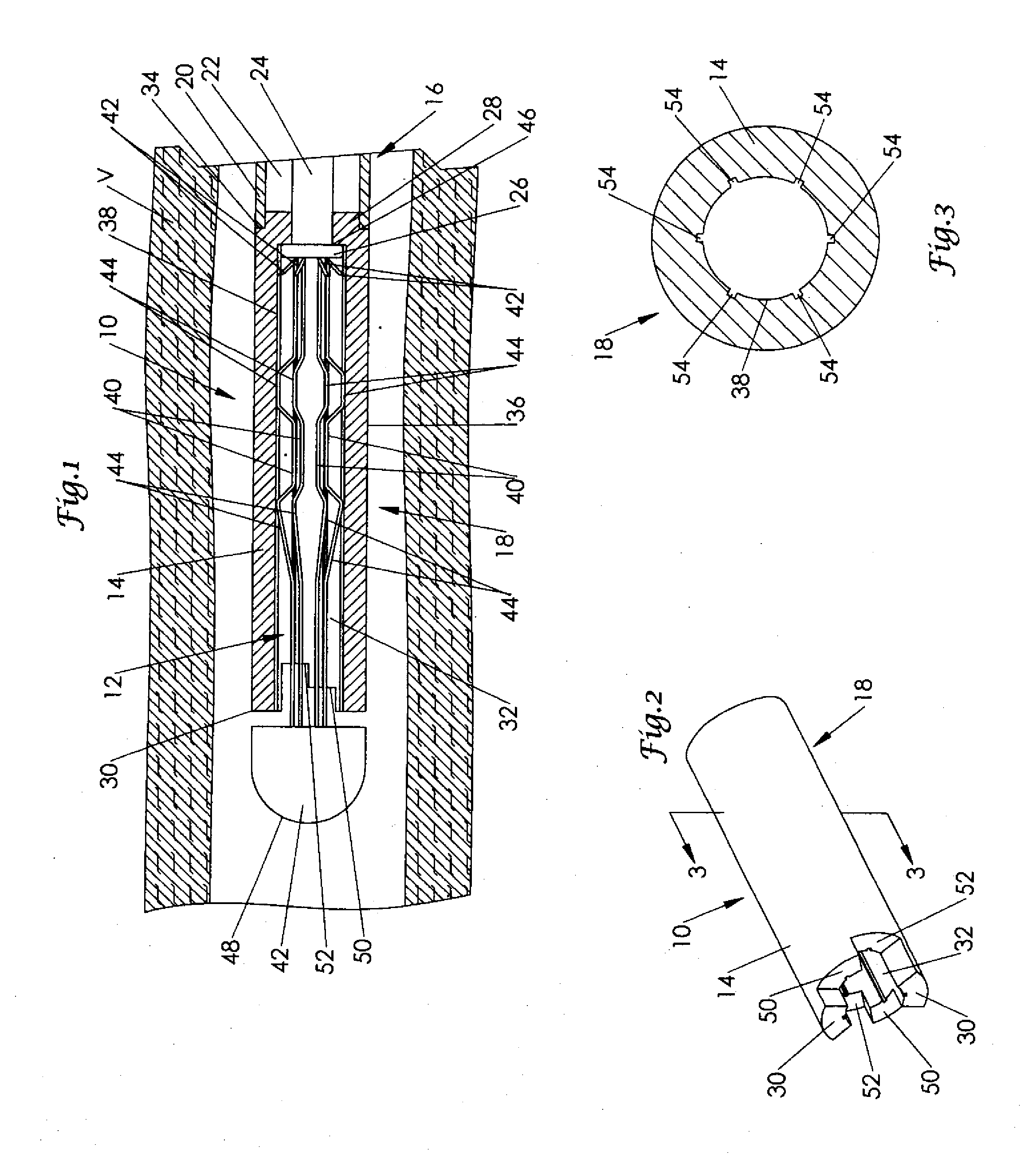
[0016]FIG. 1 is a partial cross-sectional view of the distal section of a catheter 10 in accordance with an exemplary embodiment of the present invention, showing a vena cava filter 12 fully loaded within the catheter. Catheter 10 is formed of an elongated tubular member 14 having a proximal section 16 and a distal section 18. In the particular view illustrated in FIG. 1 the distal section 18 of catheter 10 is shown advanced to a desired location within a vessel V, such as the...


PUM


Abstract

A catheter for stage-delivering a vena cava filter within a body lumen is disclosed. The catheter may comprise an elongated tubular member having a proximal section, a distal section, and an inner lumen configured to receive an intravascular filter. One or more notches or slits radially disposed about the distal end of the catheter may be utilized to stage-deploy the filter within the body. Several grooves or indentations disposed along an inner surface of the catheter may also be employed.

Description

RELATED APPLICATIONS[0001]This application is a divisional application of U.S. application Ser. No. 10 / 280,181 filed Oct. 25, 2002.FIELD OF THE INVENTION[0002]The present invention relates generally to the field of vena cava filters. More specifically, the present invention pertains to devices for delivering vena cava filters within the body.BACKGROUND OF THE INVENTION[0003]Vena cava filters are typically used in combination with other thrombolytic agents to treat pulmonary embolism occurring within a patient. These devices are generally implanted within a vessel such as the inferior vena cava, and function by capturing blood clots (emboli) contained in the blood stream before they can reach the lungs and cause permanent damage to the patient. To trap emboli contained within the blood, many conventional vena cava filters utilize a plurality of independent filter legs that can be expanded within the body to form a conical-shaped surface that captures blood clots without disturbing th...

Claims


Application Information

Patent Timeline
Patent Type & Authority Applications(United States)
IPC IPC(8): A61M29/00A61B17/22A61F2/01
CPCA61F2/01A61F2002/011A61F2230/0067A61F2230/005A61F2002/016A61F2/0105A61F2/011
Inventor WASDYKE, JOEL M.
Owner LIFESCREEN SCI
Why Eureka
Try Eureka