Placement system for a flying kite-type wind-attacked element in a wind-powered watercraft

a technology of positioning system and kite, which is applied in the field of system for deployment of a freely flying kitelike element, can solve the problems of not having the ability to deploy a relatively large element, driving in the form of an additional parachute, etc., and achieve the effect of minimizing the listing of the watercra

Active Publication Date: 2009-10-29
SKYSAILS GMBH & CO KG
View PDF17 Cites 13 Cited by
  • Summary
  • Abstract
  • Description
  • Claims
  • Application Information

AI Technical Summary

Benefits of technology

[0005]Measures for a deployment system make it possible to launch a system on which wind acts in a manner which is compatible with practical use at sea, and to be stowed safely again as well. In particular, one aim in this case is to ensure that the element on which wind acts can be guided from the deck in the deployed state, thus minimizing the listing of the watercraft.
[0006]For stowage, the element on which wind acts can be guided to a position in which it can be stowed safely and without problems.
[0007]In this case, it is particularly advantageous to provide a holder which can be pivoted in azimuth, by means of which the element on which wind acts can on the one hand be moved for deployment to a position in which it is subject to sufficient wind effect. A docking receptacle apparatus for detachable connection to the docking adapter of the element on which wind acts in this case is in each case directed to the side facing away from the wind, in which case both driven readjustment means and a type of “wind vane” can be provided. The docking receptacle apparatus is in this case designed such that it also allows locking, by holding means which engage automatically, for stowage of the element on which wind acts.

Problems solved by technology

This deployment system, which is indicated only in the form of a sketch in the cited publication and has not been fully developed, has the disadvantage that an auxiliary drive in the form of an additional parachute is required for deployment of the element on which wind acts.
Furthermore, no measures are evident to allow a relatively large element on which wind acts also to be stowed safely again.

Method used


Image

  • Placement system for a flying kite-type wind-attacked element in a wind-powered watercraft
  • Placement system for a flying kite-type wind-attacked element in a wind-powered watercraft
  • Placement system for a flying kite-type wind-attacked element in a wind-powered watercraft

Examples


Embodiment Construction

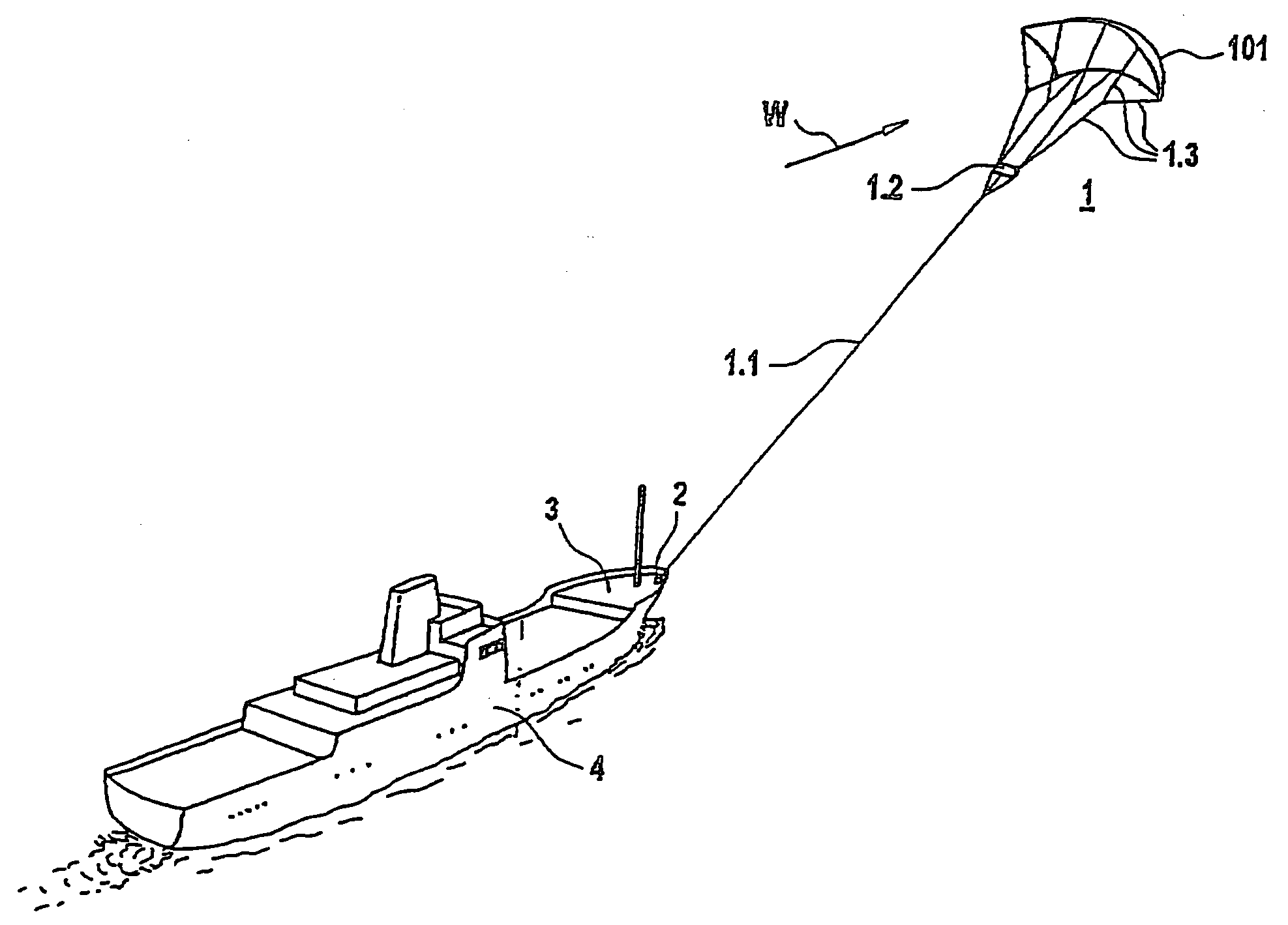
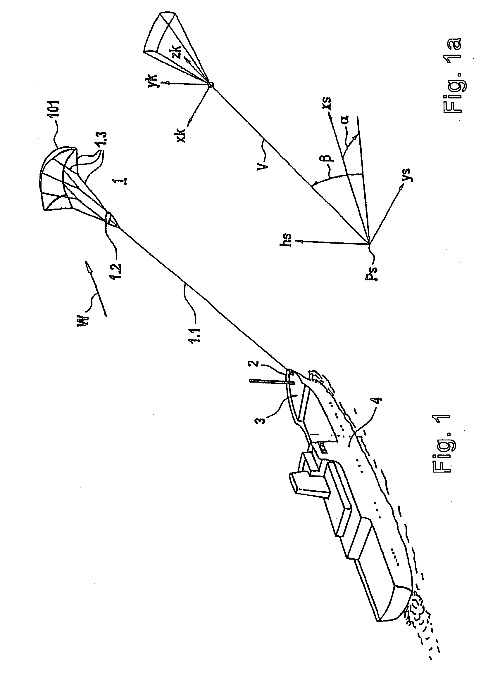
[0043]FIG. 1 shows an oblique plan view of a vessel which is being towed by the kite system. In this case, an element 1 on which wind acts is connected to a vessel 4 via a hawser 1.1 with an apparatus 2 on which force acts and which is provided in the bow area of the vessel 4. The hawser 1.1 is passed to a central gondola 1.2, from which a number of holding lines 1.3 originate, which are passed to the element 1 on which wind acts and is in the form of a paraglider with a kite profile, giving it the necessary shape. The details relating to this will be explained further below in the description. The apparent wind direction in the area of the element 1 on which wind acts is annotated W. The corresponding wind vector is indicated by its magnitude and direction. If required, its rate of change is also indicated by a variable B, which denotes the gusting, forms the mean time discrepancy between the wind speed and its mean value and can be represented as a scalar, which effectively forms ...


PUM


Abstract

Disclosed is a placement system for a free-flying kite-type wind-attacked element in a watercraft in which the kite-type wind-attacked element comprising a profiled wing is connected to the vessel body via a traction rope. Said wind-attacked element can be guided from a neutral position on board the watercraft into a raised position that is free from obstacles located at the same or a higher level. An azimuthally pivotable fixture is provided by means of which the wind-attacked element can be brought into a position in which the same is exposed to a sufficient wind effect. Furthermore, a docking receiving device is provided which is to be removably connected to the docking adapter of the wind-attacked element on the side facing away from the wind while also allowing the wind-attacked element to be furled with the aid of automatically engaging holding means.

Description

RELATED APPLICATION[0001]This application is a continuation-in-part of, and claims the benefit of, U.S. application Ser. No. 11 / 578,860 filed Oct. 10, 2006 for Placement System For A Flying Kite-Type Wind-Attacked Element In A Wind-Powered WatercraftBACKGROUND OF THE INVENTION[0002]The invention relates to a system for deployment of a freely flying kite-like element on which wind acts, for a watercraft with wind propulsion.[0003]A deployment system such as this for a freely flying kite-like element on which wind acts is known from the document: Ship Propulsive Kites, An Initial Study, by J. F. Wellicome and S. Williams, University of Southampton, ISSN 0140 3818 SSSU19, Section 4.1.2 “Non Powered Drogue Launch”.[0004]This deployment system, which is indicated only in the form of a sketch in the cited publication and has not been fully developed, has the disadvantage that an auxiliary drive in the form of an additional parachute is required for deployment of the element on which wind ...

Claims


Application Information

Patent Timeline
Patent Type & Authority Applications(United States)
IPC IPC(8): B63H9/04B63H9/06B63H9/08
CPCB63H9/0685B63H9/069
Inventor WRAGE, STEPHANBOHM, JOHANNES
Owner SKYSAILS GMBH & CO KG
Why Eureka
Try Eureka