Connector

Inactive Publication Date: 2009-10-29
KYOCERA CORP
View PDF6 Cites 9 Cited by
  • Summary
  • Abstract
  • Description
  • Claims
  • Application Information

AI Technical Summary

Benefits of technology

[0016]It is desirable for the locking protrusion to protrude from one of a top surface and a bottom surface of the contact, and for the holding portion to be formed on one of a top surface and a bottom surface of the contact support groove. Accordingly, the position of the contact relative to the insulator can be securely fixed.
[0017]It is desirable for an engaging portion to be formed on the contact at a position different from a position of the locking protrusion in a l

Problems solved by technology

Additionally, if each partition wall is thin, a stress applied to each partition wall which is caused by press-fitting the plurality of contacts into the corresponding plurality of contact support grooves cannot be sufficiently dispersed and thus remains, so that there is a possibility of the entire housing becoming warped.
Specificall

Method used


Image

  • Connector
  • Connector
  • Connector

Examples


Example

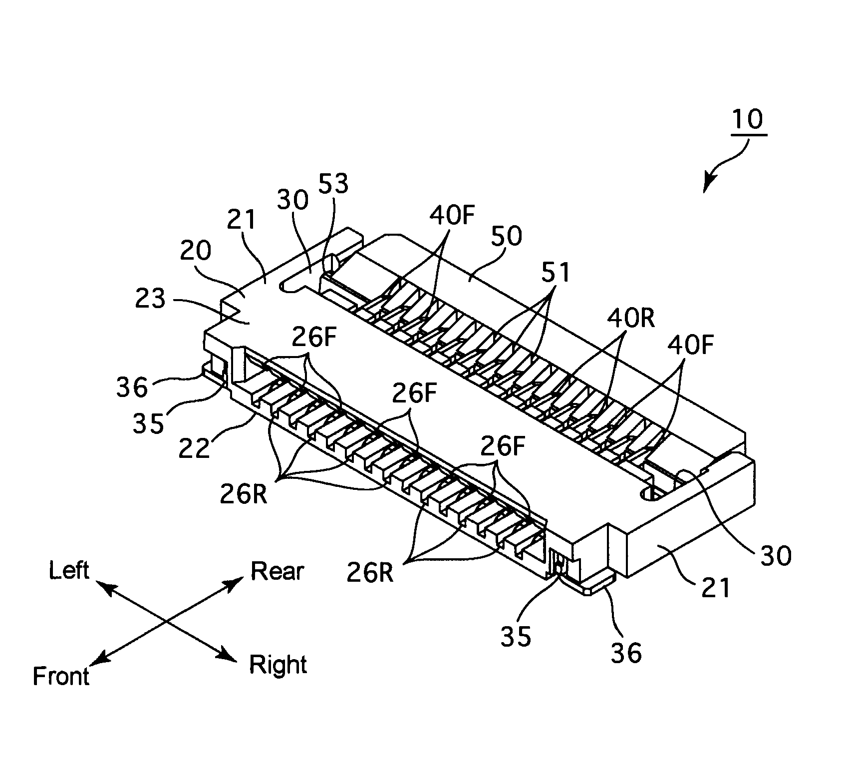
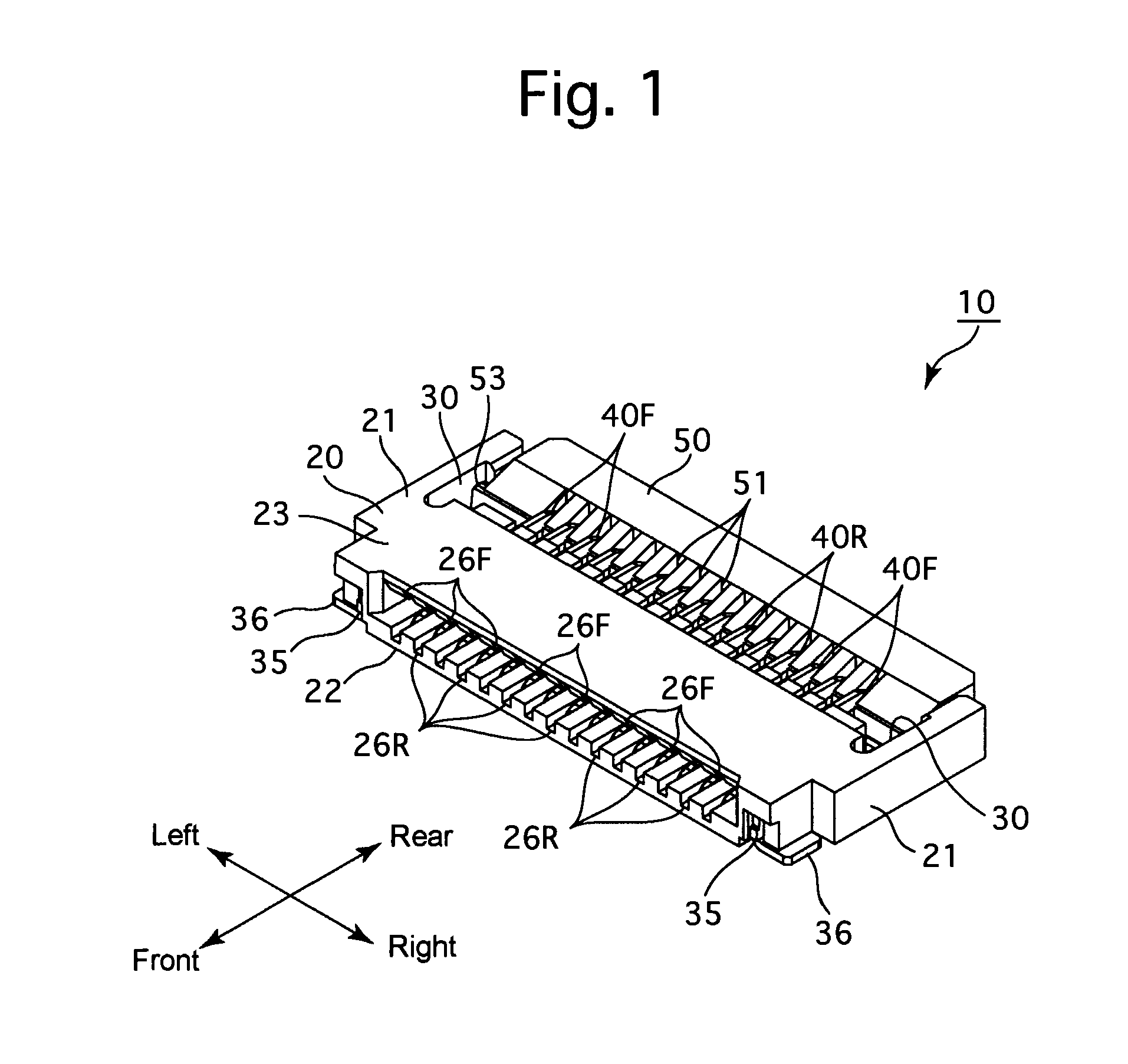
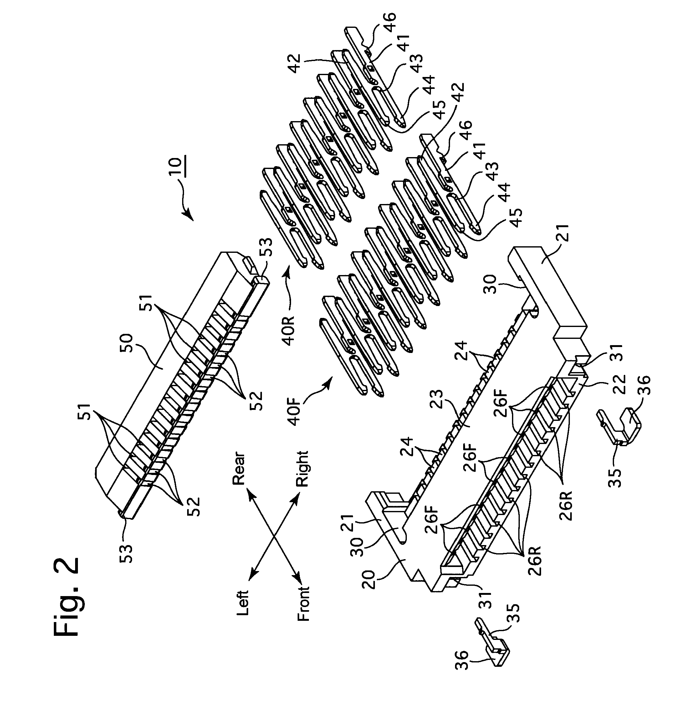
[0040]An embodiment of a connector according to the present invention will be hereinafter discussed with reference to FIGS. 1 through 10. In the following descriptions, forward and rearward directions, leftward and rightward directions, and upward and downward directions of the connector 10 are determined with reference to the directions of the double-headed arrows shown in the drawings.

[0041]The connector 10 is for use with a FPC (Flexible Printed Circuit). The connector 10 is provided, as relatively large elements thereof, with an insulator 20, two (left and right) anchors 35, a series of first contacts 40F, a series of second contacts 40R and a rotational actuator 50.

[0042]The insulator 20 is made of electrical-insulative and heat-resistant synthetic resin by injection molding. The insulator 20 is provided with a pair of (left and right) sidewall portions 21, a bottom plate portion 22 and a top plate portion 23. The bottom ends of the pair of side wall portions 21 are connected t...


PUM


Abstract

A connector to which an object is to be connected, includes an insulator having at least one contact support groove, and at least one contact which is fixed to the insulator by being inserted into the contact support groove, the contact being contactable with the object after the object is inserted into the insulator. The insulator includes at least one holding portion formed as one of a recess and a through-hole, which is communicatively connected with the contact support groove, and the contact includes a locking protrusion, which comes into engagement with the holding portion to hold the contact to the insulator when the contact is inserted into the contact support groove.

Description

CROSS REFERENCE TO RELATED APPLICATION[0001]The present invention is related to and claims priority of the following co-pending application, namely, Japanese Patent Application No. 2008-112119 filed on Apr. 23, 2008.FIELD OF THE INVENTION[0002]The present invention relates to a connector.BACKGROUND OF THE INVENTION[0003]The connector disclosed in Japanese Unexamined Patent Publication 2008-60087 is provided with a housing (insulator) having a plurality of contact support grooves (insertion grooves), a plurality of contacts which are respectively inserted into the plurality of contact support grooves by press-fitting, and a slider (actuator) supported by the housing.[0004]Since a fixed portion in the shape of a projection projects from a side of each contact, inserting each contact into a corresponding contact support groove by press-fitting causes the fixed portion of this contact to be pressed against a side surface of associated one of a plurality of partition walls, defining the ...

Claims


Application Information

Patent Timeline
IPC IPC(8): H01R24/00
CPCH01R12/57H01R12/88H01R12/79H01R13/422
Inventor SATOH, TOMOYUKIFUKUOKA, ATSUNOBU
Owner KYOCERA CORP
Why Eureka
Try Eureka