Map display system, map display device, map display method, and map distribution server

a map display system and map technology, applied in surveying and navigation, instruments, navigation instruments, etc., can solve the problem of not being able to clearly distinguish which objects, and achieve the effect of reliably distinguishing the desired object and quick selection

Inactive Publication Date: 2009-10-29
NAVITIME JAPAN CO LTD
View PDF37 Cites 29 Cited by
  • Summary
  • Abstract
  • Description
  • Claims
  • Application Information

AI Technical Summary

Benefits of technology

[0032]In the first aspect of the invention, when the cursor location is over the object image of the target object, the object display control means preferably changes and draws the object image and cursor image display configurations, and the cursor operation sensing means preferably enables the display of the object information related to the target object to be controlled.
[0058]In the first aspect of the invention, the map display system comprises target object determination means for calculating the distance between the cursor position and the position of each object image to determine the object having the shortest distance, wherein the object display control means re-draws the object image of the target object determined by the target object determination means and displays the image on the uppermost surface of the displayed images.
[0059]According to this configuration, because the object image nearest the cursor position is always displayed on the uppermost surface of the display screen, when the user selects the desired object image with the cursor, the desired object image can be displayed on the uppermost surface of the screen and selected simply by moving the cursor, allowing the object image to be rapidly selected. It also becomes possible to reliably distinguish the desired object that is to be manipulated.
[0061]According to this configuration, the object image where the cursor is located can be readily distinguished, and the display of the detailed information for the corresponding object can be controlled only when the object image where the cursor is located is clicked, thus preventing detailed information for objects not on the uppermost surface to be displayed even when those objects are accidentally selected with the cursor.
[0062]In the first aspect of the invention, the cursor is preferably a cross-shaped cursor, and when the cursor location is over the object image of the target object, the object image is preferably re-drawn as a display configuration emphasizing the object image, and the cursor display configuration is preferably specified and changed to an image. According to this configuration, the user can readily distinguish that the cursor has been manipulated to select the desired object image.
[0063]In the first aspect of the invention, when the object comprises different objects located in a building of a same establishment, the center position of each object image is preferably set so as to be in a different location, and the object display control means preferably displays object images based on the location information for each of the object images. According to this configuration, different objects in the same building can be displayed without overlapping.

Problems solved by technology

Even when the user moves the cursor in order to select an object, a drawback in such display scenarios is that it may not be possible to clearly distinguish which object image is to be selected by the cursor.

Method used


Image

  • Map display system, map display device, map display method, and map distribution server
  • Map display system, map display device, map display method, and map distribution server
  • Map display system, map display device, map display method, and map distribution server

Examples


Embodiment Construction

[0102]Specific examples of the present invention will be described in detail below with reference to the embodiments and drawings. However, the embodiments described below are used to exemplify a map display device and map display method for implementing the technical concepts of the present invention, are not intended to limit the present invention to this map display method and map display method, and are also equally applicable to map display devices and map display systems of other embodiments within the scope of the claims.

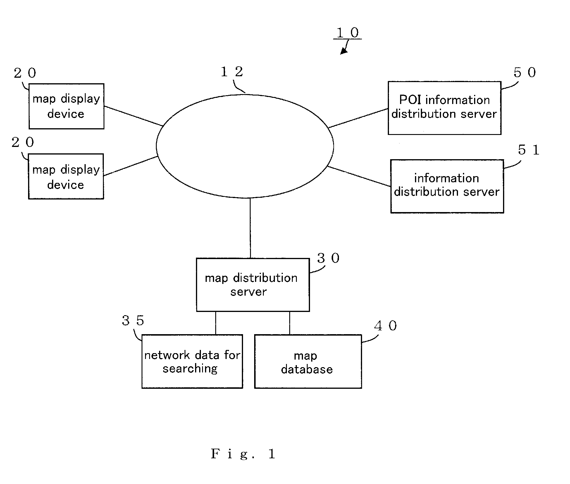
[0103]FIG. 1 is a structural diagram of a system showing the configuration of a map display system 10 including the map display device 20 according to the present invention. As shown in FIG. 1, the map display system 10 comprises a map display device 20 and a map distribution server 30 having a navigation function connected through a network 12. The map display system 10 thus functions as a navigation system.

[0104]The map display system 10 is also composed of...


PUM


Abstract

A map display system having display means for displaying a map image and object display control means for displaying object images on the map image according to the location of the objects, wherein, when a cursor is moved to a desired object image and operated to select it, information on the object is displayed. The map display system has target object determination means for calculating the distances between the cursor and the individual object images and determining an object of the smallest distance to the cursor. The object display control means re-draws an object image of the target object determined by the target object determination means and displays the result on the uppermost surface of an image displayed. When a large number of object images are displayed on a map image, in areas close to each other, the user can simply recognize a desired object image and can click the object image accurately and reliably.

Description

TECHNICAL FIELD[0001]The present invention relates to a map display system for displaying a map image on a display component, a map display device, and a map display method, as well as a map distribution server. In this type of map display system, an object image displays an object such as a store or establishment on a map image, and a cursor is moved onto the displayed object image and clicked to open a window for displaying detailed information on the object.[0002]The present invention particularly relates to a map display system, a map display device, and a map display method, as well as a map distribution server, wherein, when a large number of object images such as the above are displayed in adjacent areas on a map image, the object image that is in a location where the distance from the cursor to the object image is the closest is re-drawn and displayed on the uppermost surface of the displayed images. The invention also relates to a map display system, a map display device, a...

Claims


Application Information

Patent Timeline
Patent Type & Authority Applications(United States)
IPC IPC(8): G06F3/048G06F3/0481G06F17/30
CPCG01C21/367G09B29/10G06F3/0481G01C21/3682
Inventor SAKAMOTO, HIROSHISHINOHARA, TAKEHIROKANETO, NAO
Owner NAVITIME JAPAN CO LTD
Why Eureka
Try Eureka