Portable device for supplying compressed CO2 from a pressure vessel to a pneumatic tool

a technology of compressed co2 and portability, applied in the field of pneumatic tools, can solve problems such as inconvenience to work and inability to connect reliablely

Inactive Publication Date: 2009-11-05
FEVER INDAL
View PDF7 Cites 48 Cited by
  • Summary
  • Abstract
  • Description
  • Claims
  • Application Information

AI Technical Summary

Problems solved by technology

The main problem of the patent is detailed below.
However, the connections are not reliable due to high air pressure.
Further, in use a worker has to wear the device on the belt with the container enclosed in a bag.
This may cause inconvenience to work.

Method used


Image

  • Portable device for supplying compressed CO2 from a pressure vessel to a pneumatic tool
  • Portable device for supplying compressed CO2 from a pressure vessel to a pneumatic tool
  • Portable device for supplying compressed CO2 from a pressure vessel to a pneumatic tool

Examples


Embodiment Construction

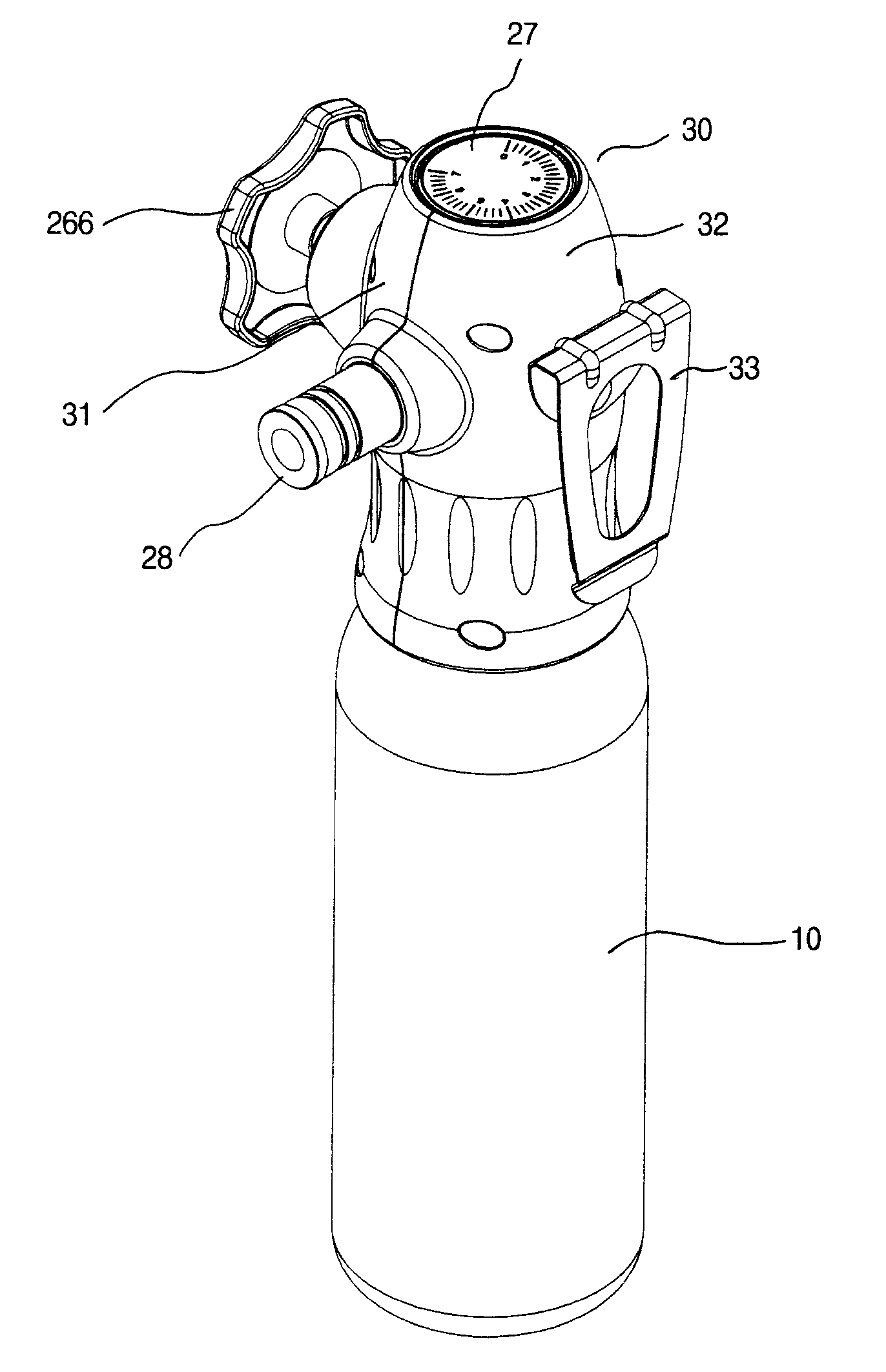
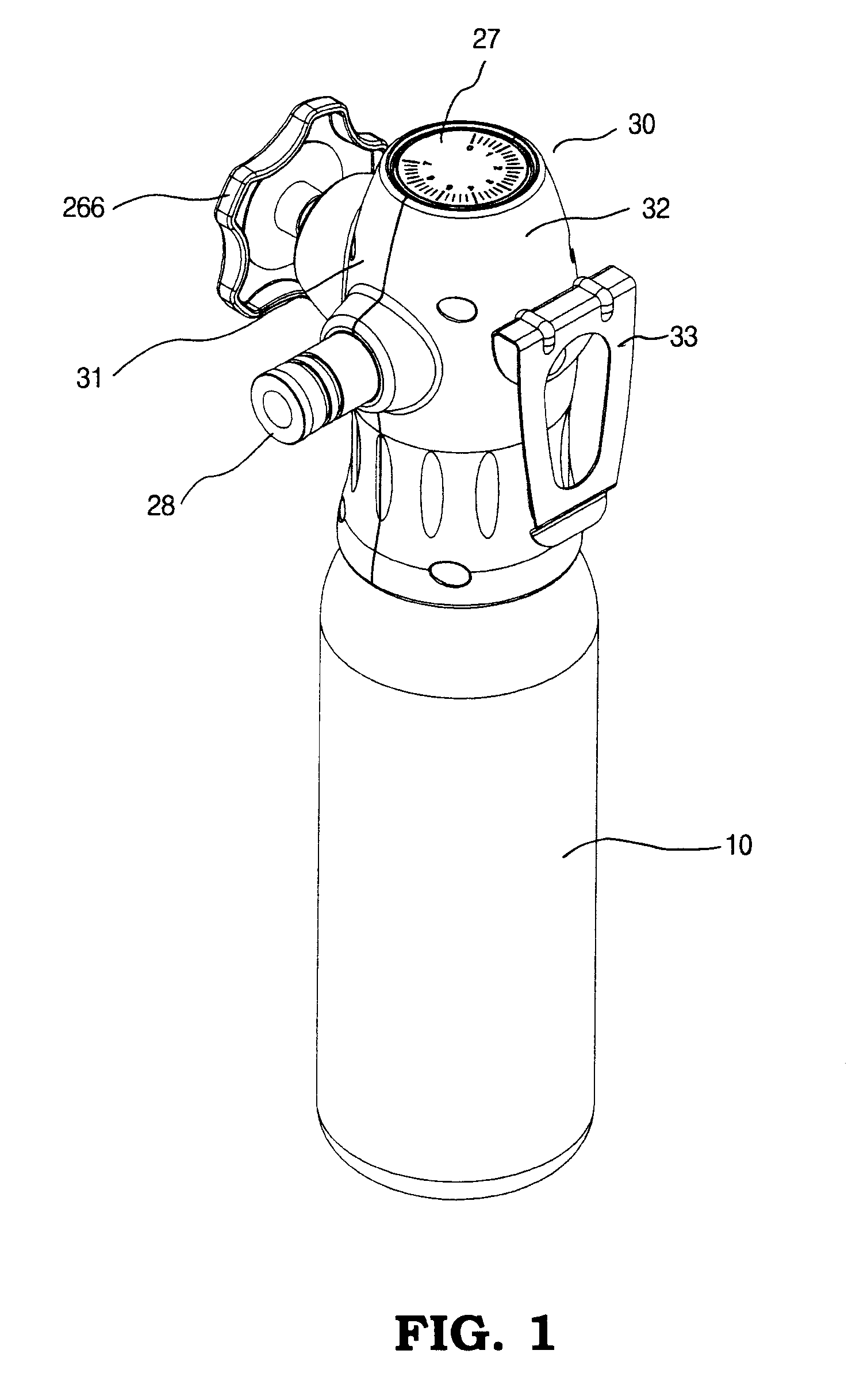
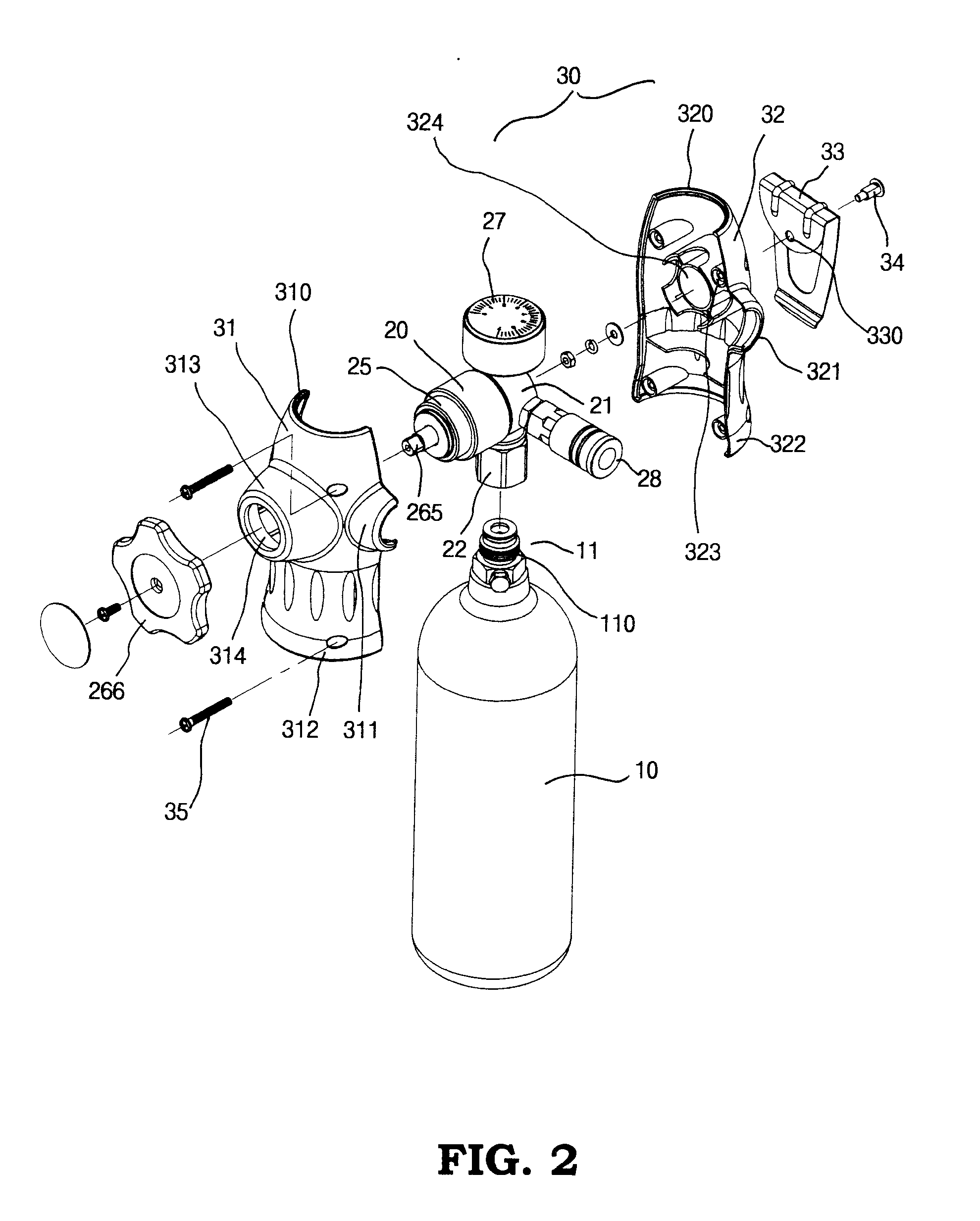
[0018]Referring to FIGS. 1 to 10, a portable device for supplying compressed air in accordance with a preferred embodiment of the invention is shown. The device comprises a cylindrical pressure vessel 10 filled with compressed CO2, the pressure vessel 10 having a valve 11 on the top of a dome shaped upper portion thereof, the valve 11 having an externally threaded section 110 and a needle member 111; a pressure regulator 20; and a housing 30.

[0019]The pressure regulator 20 comprises a hollow cylindrical body 21 having a blind bottom, the body 21 including a control chamber 210 defined therein, an inlet 211 on the circumferential surface, an outlet 212 on the circumferential surface spaced from the inlet 211 in an angle about 90 degrees, a relief valve fixing hole 213 on the circumferential surface opposing the outlet 212, and a pressure gauge fixing hole 214 on the circumferential surface opposing the outlet 212. That is, the inlet 211, the outlet 212, the pressure gauge fixing hole...


PUM


Abstract

A device includes a pressure regulator comprising a body including a control chamber adapted to connect to a portable pressure vessel filled with compressed CO2 via an inlet coupling, the control chamber having a threaded stepped diameter passageway, a relief valve, and a pressure gauge, a valve, a cap including a hand wheel, and a pressure adjustment assembly including a resilient sealing disk, a disc, a thumbtack member, a fastener for securing the thumbtack member and the sealing disk together, and a spring biased between the sealing disk and the disc; a housing for partially enclosing the pressure regulator with the hand wheel, the pressure gauge, and an outlet coupling being exposed; and a hanging member pivotably secured onto the housing.

Description

BACKGROUND OF THE INVENTION[0001]1. Field of Invention[0002]The invention relates to pneumatic tools and more particularly to an improved device for supplying compressed CO2 from a pressure vessel to a pneumatic tool (e.g., pneumatic nail gun, pneumatic screwdriver, pneumatic wrench, etc.), whereby a user can continuously operate the pneumatic tool in a safety manner.[0003]2. Description of Related Art[0004]The invention described later is an outgrowth of earlier work by the inventor hereof, described in U.S. Pat. No. 7,325,397, the teachings of which are incorporated herein by reference.[0005]The main problem of the patent is detailed below. The container and the pressure-reducing chamber are interconnected by a hose. However, the connections are not reliable due to high air pressure. Hence, it has a safety concern. Further, in use a worker has to wear the device on the belt with the container enclosed in a bag. This may cause inconvenience to work. Thus, the need for improvement s...

Claims


Application Information

Patent Timeline
Patent Type & Authority Applications(United States)
IPC IPC(8): F15B13/02F16K31/12F17C1/00
CPCF16K1/306G05D16/0663F17C2201/0119F17C2201/037F17C2201/058F17C2203/0617F17C2205/0157F17C2205/0308F17C2205/0329F17C2205/0332F17C2205/0338F17C2205/037F17C2205/0382F17C2205/0394F17C2209/228F17C2221/013F17C2223/0123F17C2223/035F17C2250/043F17C2250/0491F17C2250/0626F17C2260/00F17C2270/0563F17C13/04Y10T137/7794Y10T137/7826
Inventor LEE, CHI PING
Owner FEVER INDAL
Why Eureka
Try Eureka