Infusion pump assembly

a technology of infusion pump and assembly, which is applied in the direction of volume measurement, special dispensing means, packaging goods types, etc., can solve the problems of difficult patient maintenance of desired schedule, high malfunction rate, and many potentially valuable medicines or compounds, including biologicals, that are not orally active,

Active Publication Date: 2009-11-05
DEKA PROD LLP
View PDF101 Cites 144 Cited by
  • Summary
  • Abstract
  • Description
  • Claims
  • Application Information

AI Technical Summary

Benefits of technology

[0007]One or more of the following features may be included. The wearable infusion pump assembly may also include a disposable housing assembly including the reservoir and a first portion of the fluid delivery system. The wearable infusion pump assembly may also include a reusable housing assembly including a second portion of the fluid delivery system. A first portion of the pump assembly may be positioned within the disposable housing assembly. A second portion of the pump assembly may be positioned within the reusable housing assembly. A first portion of the first valve assembly may be positioned within the disposable housing assembly. A second portion of the first valve assembly may be positioned within the reusable housing assembly. A first portion of the second valve assembly may be positioned within the disposable housing assembly. A second portion of the second valve assembly may be positioned within the reusable housing assembly.

Problems solved by technology

Many potentially valuable medicines or compounds, including biologicals, are not orally active due to poor absorption, hepatic metabolism or other pharmacokinetic factors.
Additionally, some therapeutic compounds, although they can be orally absorbed, are sometimes required to be administered so often it is difficult for a patient to maintain the desired schedule.
These devices suffer from a number of drawbacks including the malfunction rate.
Reducing the size, weight and cost of these devices is also an ongoing challenge.
Additionally, these devices often apply to the skin and pose the challenge of frequent re-location for application.

Method used


Image

  • Infusion pump assembly
  • Infusion pump assembly
  • Infusion pump assembly

Examples


Embodiment Construction

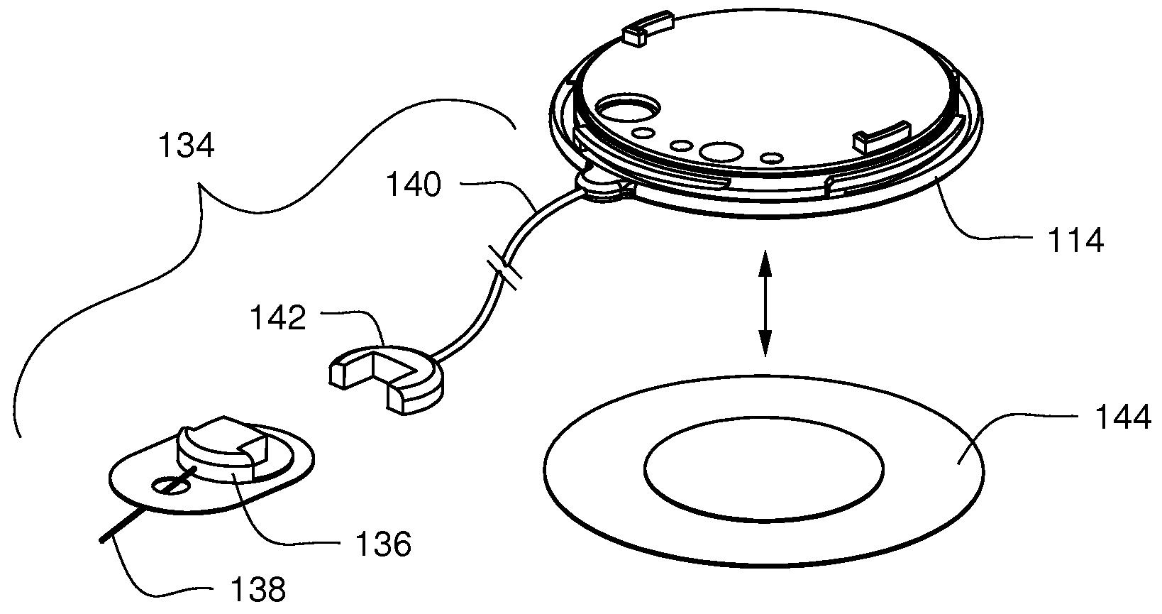
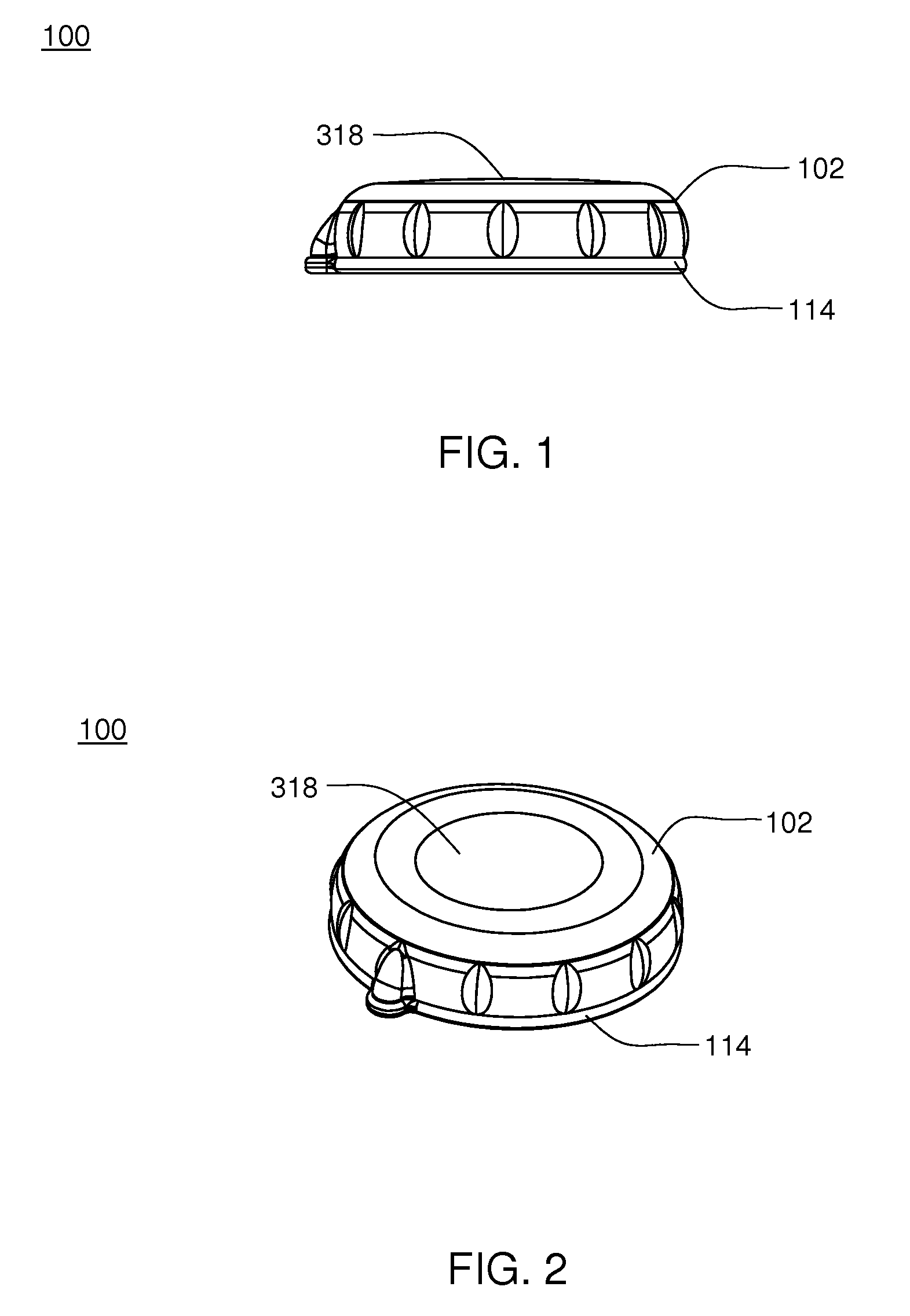
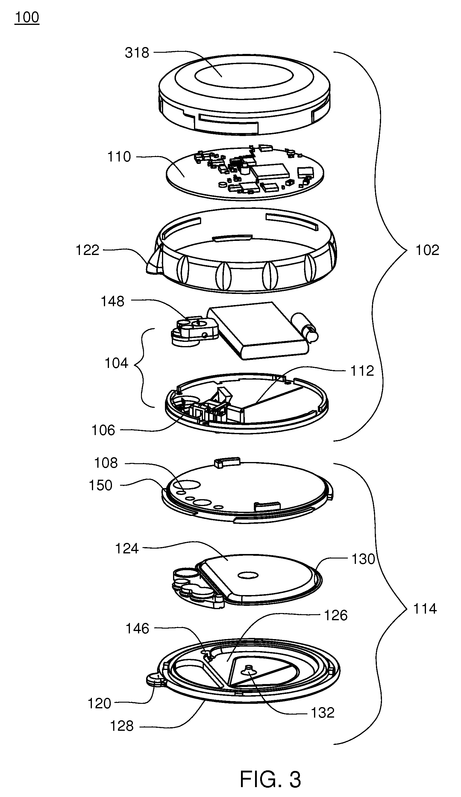
[0134]Referring to FIGS. 1-3, an infusion pump assembly 100 may include a reusable housing assembly 102. Reusable housing assembly 102 may be constructed from any suitable material, such as a hard or rigid plastic, that will resist compression. For example, use of durable materials and parts may improve quality and reduce costs by providing a reusable portion that lasts longer and is more durable, providing greater protection to components disposed therein.

[0135]Reusable housing assembly 102 may include mechanical control assembly 104 having a pump assembly 106 and at least one valve assembly 108. Reusable housing assembly 102 may also include electrical control assembly 110 configured to provide one or more control signals to mechanical control assembly 104 and effectuate the basal and / or bolus delivery of an infusible fluid to a user. Disposable housing assembly 114 may include valve assembly 108 which may be configured to control the flow of the infusible fluid through a fluid pa...


PUM

PropertyMeasurementUnit
timeaaaaaaaaaa
lengthaaaaaaaaaa
timeaaaaaaaaaa

Abstract

A wearable infusion pump assembly includes a reservoir for receiving an infusible fluid, and an external infusion set configured to deliver the infusible fluid to a user. A fluid delivery system is configured to deliver the infusible fluid from the reservoir to the external infusion set. The fluid delivery system includes a volume sensor assembly, and a pump assembly for extracting a quantity of infusible fluid from the reservoir and providing the quantity of infusible fluid to the volume sensor assembly. The volume sensor assembly is configured to determine the volume of at least a portion of the quantity of fluid. The fluid delivery system further includes a first valve assembly configured to selectively isolate the pump assembly from the reservoir, and a second valve assembly configured to selectively isolate the volume sensor assembly from the external infusion set.

Description

CROSS REFERENCE TO RELATED APPLICATION(S)[0001]This application is a continuation-in-part of application Ser. No. 11 / 704,899 filed Feb. 9, 2007, which claims the priority of the following patent applications, each of which is herein incorporated by reference in its entirety: Ser. Nos. 11 / 704,896 filed Feb. 9, 2007; 11 / 704,886 filed Feb. 9, 2007; 11 / 704,897 filed Feb. 9, 2007; which claim the benefit of the following provisional patent applications, each of which is herein incorporated by referenced in its entirety: Nos. 61 / 018,054 filed Dec. 31, 2007; 61 / 018,042 filed Dec. 31, 2007; 61 / 027,989 filed Dec. 31, 2007; 61 / 018,002 filed Dec. 31, 2007; 61 / 018,339 filed Dec. 31, 2007; 61 / 023,645 filed Jan. 25, 2008; 61 / 101,053 filed Sep. 29, 2008; 61 / 101,077 filed Sep. 29, 2008; and 61 / 101,105 filed Sep. 29, 2008.FIELD OF THE INVENTION[0002]This application relates generally to fluid delivery systems, and more particularly to infusion pump assemblies.BACKGROUND[0003]Many potentially valuabl...

Claims


Application Information

Patent Timeline
Patent Type & Authority Applications(United States)
IPC IPC(8): A61M5/142B67D7/08B67D7/14
CPCA61M2205/3331Y10T29/49826A61M2205/3546A61M2205/3576A61M2205/8237A61M2206/22A61M2209/045G05D7/0647G05D7/0676A61M5/14224A61M5/14248A61M5/14586A61M5/16809A61M5/16886A61M2005/14268A61M2205/0266A61M2205/0294A61M2205/18G08C17/02H04B7/2609A61M5/172A61M5/168G05B23/02A61M5/1452A61M5/14244A61M2207/00A61M5/158A61M5/1723A61M5/142Y10T29/49412Y10T29/49236Y10T29/494A61M2205/3375A61M5/1413A61M2205/6018A61M2205/3569A61M2209/086A61M2205/50Y02A90/10F04B43/02Y10T29/49828A61B5/0024A61B5/1427A61B5/6833A61B2560/0412A61J1/20A61M5/14212A61M5/14216A61M5/162A61M5/16804A61M5/16813A61M5/16831A61M5/365A61M5/5086A61M2005/1402A61M2005/14208A61M2005/14252A61M2005/14506A61M2005/1583A61M2005/1585A61M2005/1586A61M2005/16863A61M2205/04A61M2205/16A61M2205/3303A61M2205/3337A61M2205/3368A61M2205/3379A61M2205/3523A61M2205/3592A61M2205/502A61M2205/52A61M2205/581A61M2205/582A61M2205/583A61M2205/8206A61M2230/201F04B7/00F04B43/09F04B43/1253G01F22/00
Inventor KAMEN, DEANGRAY, LARRY BRIANLANIGAN, RICHARD J.KERWIN, JOHN MATTHEWFICHERA, STEPHEN LEWIS
Owner DEKA PROD LLP
Why Eureka
Try Eureka