Particle separating method

a particle and separation technology, applied in the field of particle separation method, can solve the problems of impossible repetitive separation, simple and high separation performance, etc., and achieve the effect of low cost and better separation

Inactive Publication Date: 2009-11-12
SHEEN HORN JIUNN +1
View PDF6 Cites 2 Cited by
  • Summary
  • Abstract
  • Description
  • Claims
  • Application Information

AI Technical Summary

Benefits of technology

[0008]Accordingly, the present invention is directed to a particle separating method, which has a low cost and a better separation effect.

Problems solved by technology

One of the key issues in developing these systems is how simple and high separation performance can be achieved.
Filtration has a critical drawback, namely clogging in the channel, which makes it impossible to separate repetitively.

Method used


Image

  • Particle separating method
  • Particle separating method
  • Particle separating method

Examples


Embodiment Construction

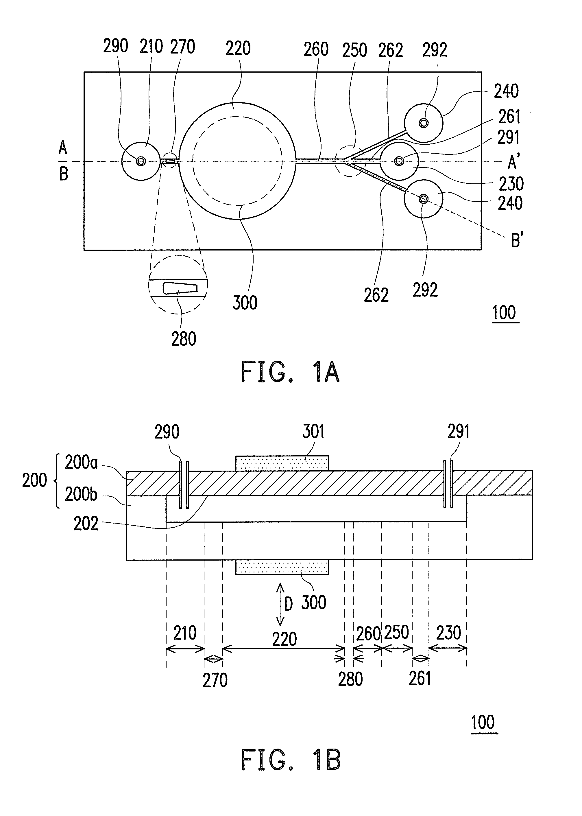
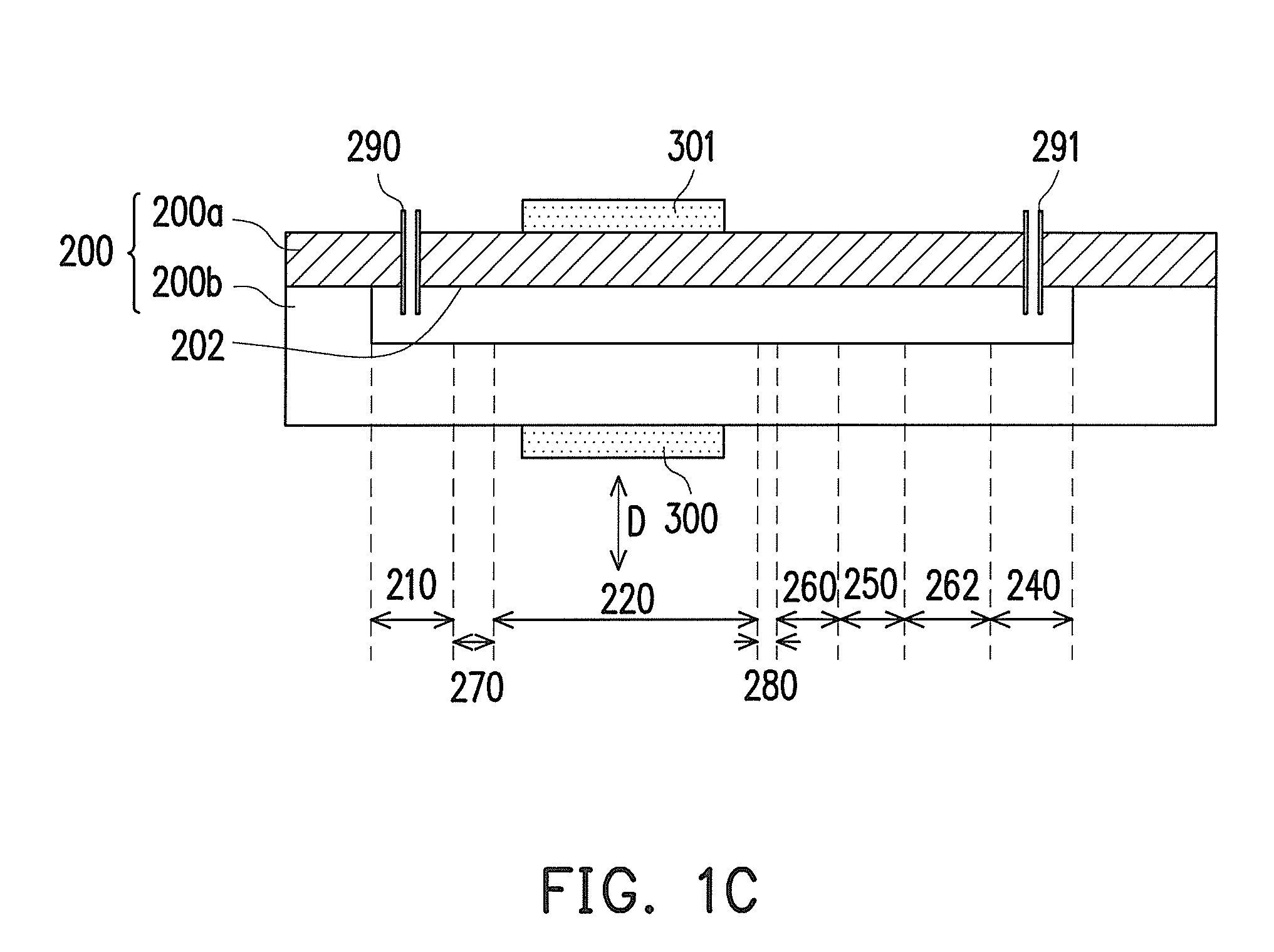
[0025]FIG. 1A is a schematic top view of a triple-channel particle separation device according to an embodiment of the present invention. FIG. 1B is a schematic sectional view of FIG. 1A taken along the line A-A′. FIG. 1C is a schematic sectional view of FIG. 1A taken along the line B-B′. FIG. 1D is a physical diagram of the triple-channel particle separation device. Referring to FIGS. 1A, 1B, 1C, and 1D, a triple-channel particle separation device 100 is suitable for separating particles contained in the suspension, in which the fluids are liquid. The triple-channel particle separation device 100 mainly includes a body 200 and a vibrating element 300. The body 200 mainly includes an upper substrate 200a and a lower substrate 200b. The upper substrate 200a is disposed on a bonding surface 202 of the lower substrate 200b, and the upper substrate 200a and the lower substrate 200b are made of, for example, glass, silicon wafer, acryl, polymethyl methacrylate (PMMA), polydimethyl siloxa...


PUM

PropertyMeasurementUnit
volumeaaaaaaaaaa
electric fieldsaaaaaaaaaa
electric fieldaaaaaaaaaa

Abstract

A particle separating method comprising the following steps is provided. A vibration chamber is vibrated by a vibrating element for changing a volume of the vibration chamber periodically, such that a suspension is pumped into the vibration chamber while the volume of the vibration chamber is increased and pumped out of the vibration chamber while the volume of the vibration chamber is decreased, and a net flow of the suspension in oscillating flow field and toward a trifurcate zone is obtained. Two vortices are generated in an upstream of a center channel of the trifurcate zone. Particles of the suspension are led toward two side channels of the trifurcate zone.

Description

CROSS-REFERENCE TO RELATED APPLICATION[0001]This is a continuation application of patent application Ser. No. 11 / 779,283, filed on Jul. 18, 2007. The entirety of the above-mentioned patent application is hereby incorporated by reference herein and made a part of this specification.BACKGROUND OF THE INVENTION[0002]1. Field of the Invention[0003]The present invention relates to a particle separating method. The suspension, which includes liquid and particles, may be pumped from the inlet chamber and the particles may be removed into the side outlet channels.[0004]2. Description of Related Art[0005]Particle separators are essential components in micro-total-analysis-systems (μ-TAS) and are widely used in bio-chemical and biomedical applications. One of the key issues in developing these systems is how simple and high separation performance can be achieved. In the previous studies, two noncontact technologies, dielectrophoresis (DEP) and acoustic wave, were the most frequently used appr...

Claims


Application Information

Patent Timeline
Patent Type & Authority Applications(United States)
IPC IPC(8): B01D43/00
CPCB01L3/502753B01L2400/0487B01L2300/0816B01L2200/0636
Inventor SHEEN, HORN-JIUNNLEE, CHING-JIUN
Owner SHEEN HORN JIUNN
Why Eureka
Try Eureka