Current detecting device

a current detection and detector technology, applied in the direction of measurement devices, magnetic measurements, instruments, etc., can solve the problems of increasing the size of the current detection device, increasing the thickness in the axial direction of the core as a whole, and increasing the cost of materials

Inactive Publication Date: 2009-11-12
TOYOTA JIDOSHA KK
View PDF3 Cites 22 Cited by
  • Summary
  • Abstract
  • Description
  • Claims
  • Application Information

AI Technical Summary

Problems solved by technology

In the above-described current detecting devices of the related art, because two Hall elements are placed side by side along the axial direction of the core, there is a problem in that the

Method used


Image

  • Current detecting device
  • Current detecting device
  • Current detecting device

Examples


embodiment

Preferred Embodiment

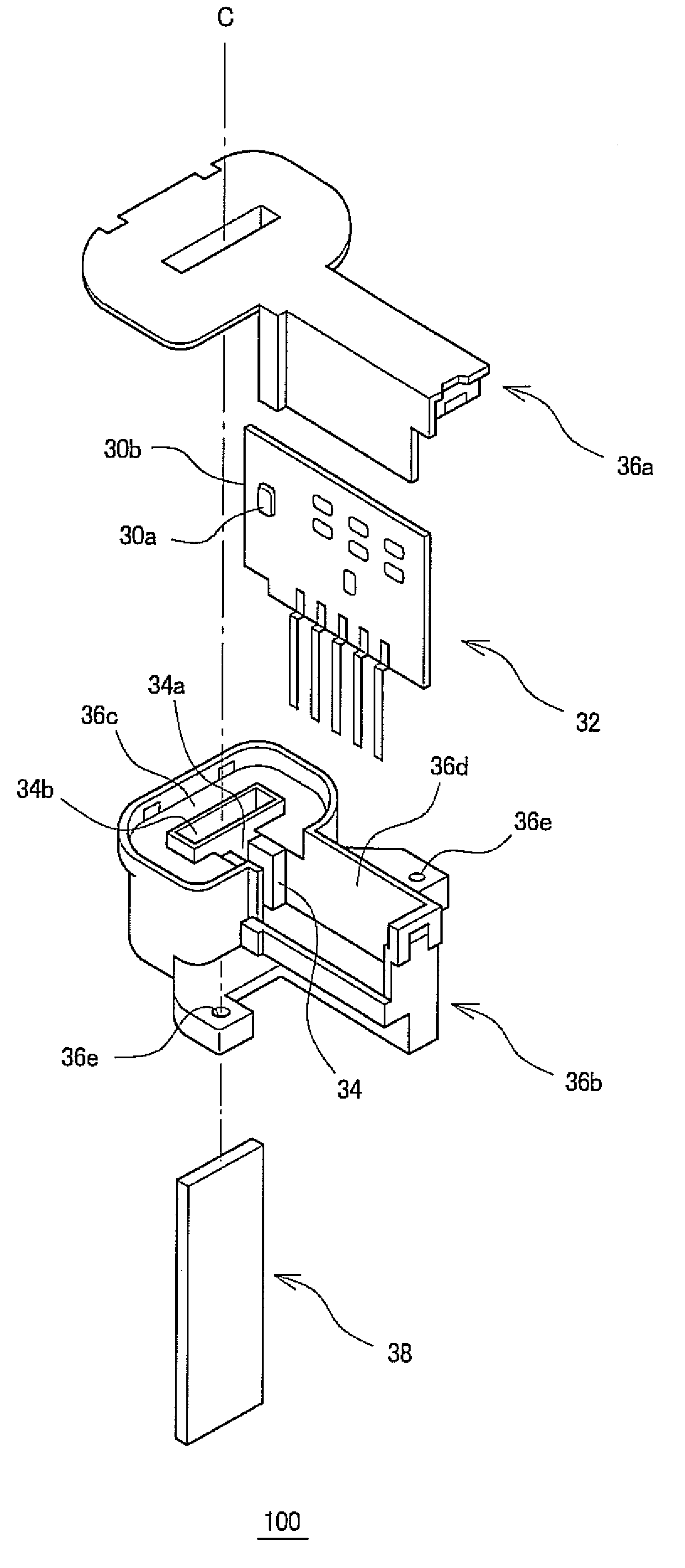
[0019]As shown in an assembly diagram of FIG. 1, a current detecting device 100 of a preferred embodiment of the present invention comprises Hall elements 30a and 30b, a sensor board 32, a core 34, core cases 36a and 36b, and a bus bar 38.

[0020]The Hall elements 30a and 30b are magnetic sensors which take advantage of the Hall effect, and are elements which convert a change of a magnetic field through the core 34 due to a change of current flowing through the bus bar 38 into an electric signal and output the electric signal.

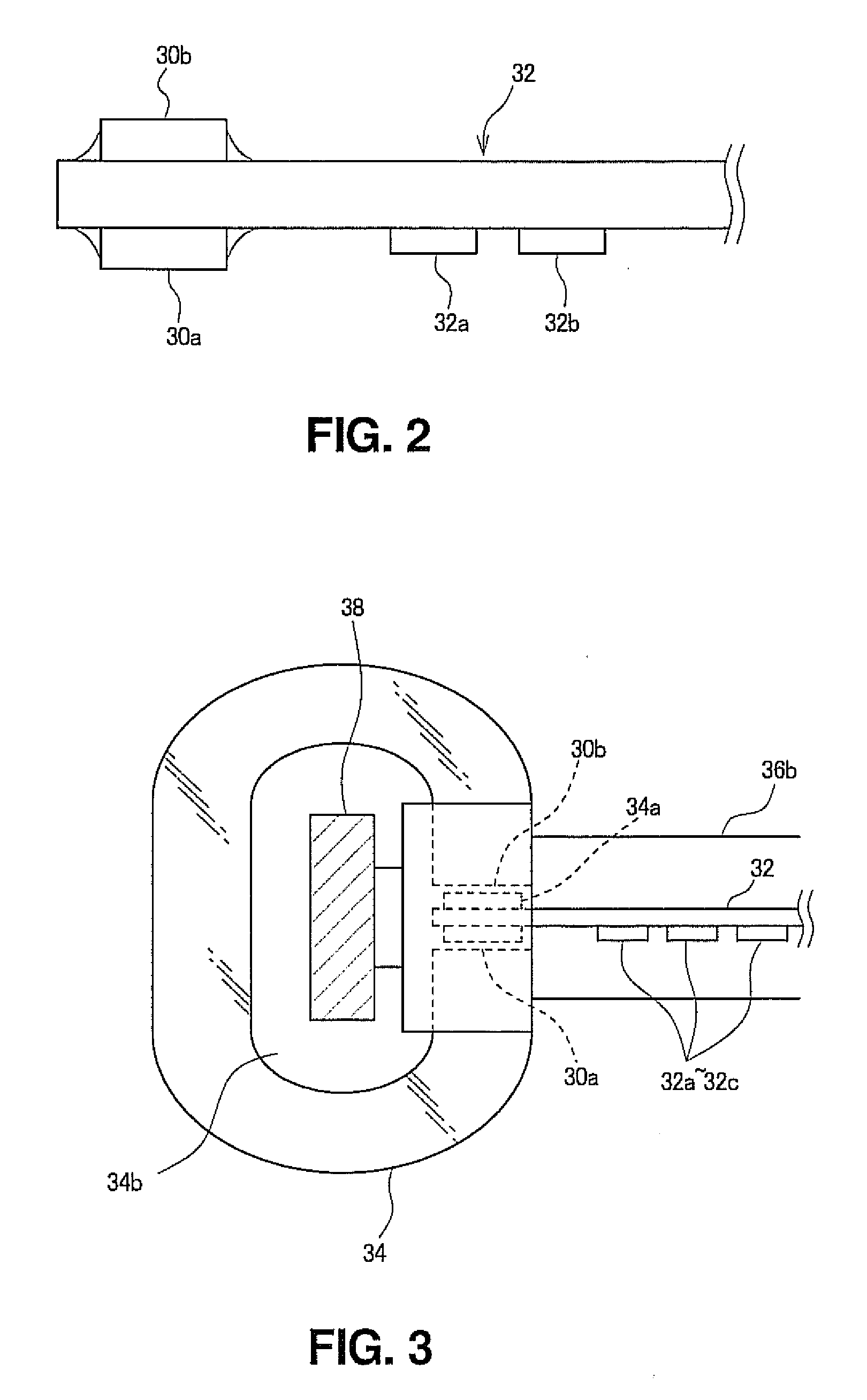
[0021]The sensor board 32 may be a printed board in which lines are patterned on a resin such as polyimide. As shown in a side view of FIG. 2, the Hall elements 30a and 30b are mounted on the sensor board 32, opposing each other with an end of the sensor board 32 therebetween. In addition, amplifier circuit elements 32a, 32b, etc. which amplify the voltages output from the Hall elements 30a and 30b are mounted on the sensor board 32. The Hall ...


PUM


Abstract

A current detecting device is provided having a plurality of Hall elements, a board on which the Hall elements are surface-mounted, and a core which surrounds a pass-through section through which a bus bar, through which a current to be detected flows, is passed and which has, at a part of the core, an opening in which the Hall element is placed, wherein the plurality of Hall elements are placed in series along a direction of a magnetic field line formed in the opening when a current flows through the bus bar. With such a structure, a core size of the current detecting device which uses the Hall element is reduced.

Description

CROSS-REFERENCE TO RELATED APPLICATION [0001]This application claims priority to Japanese Patent Application No. 2008-121089, filed on May 7, 2008.BACKGROUND OF THE INVENTION[0002]1. Field of the Invention[0003]The present invention relates to a current detecting device which takes advantage of the Hall effect.[0004]2. Description of the Related Art[0005]In electronic components equipped in a vehicle, a current detecting device in which a core, which passes a magnetic field, and a Hall element are combined is used.[0006]A current detecting device having a structure in which a Hall element and a sensor board are stored in a resin case to which a core is molded is known. In this current detecting device, as shown in an assembly diagram of FIG. 6, two Hall elements 10a and 10b are mounted on one side of a sensor board 12. A core 14, on the other hand, is formed with a tubular magnetic material having an opening 14a which is partially cut out along an axial direction A. Both of the Hall...

Claims


Application Information

Patent Timeline
IPC IPC(8): G01R19/00G01R33/07
CPCG01R15/202G01R33/07G01R33/0047
Inventor YOSHIDA, TADAFUMI
Owner TOYOTA JIDOSHA KK
Why Eureka
Try Eureka