Apparatus for reducing kv-dependent artifacts in an imaging system and method of making same

a technology of imaging system and apparatus, applied in the field of xray tubes, can solve the problems of large amount of heat generated in the anode, overheating the window and joints, and the typical volume of the electron collector is substantial,

Active Publication Date: 2009-11-12
GENERAL ELECTRIC CO
View PDF12 Cites 11 Cited by
  • Summary
  • Abstract
  • Description
  • Claims
  • Application Information

AI Technical Summary

Problems solved by technology

X-ray generation results in a large amount of heat being generated within the anode.
Much of this back-scatter energy is deposited in and around the window, which can overheat the window and the joints that attach the window to the x-ray tube.
However, the electron collector typically includes a substantial amount of mass and volume in order to both sink the heat and house the coolant lines therein.
The diffracted beam will therefore result in an area of locally increased intensity that, when impacting on the detector, may give rise to an area of increased intensity, resulting in an image artifact.
Therefore, if x-rays of characteristic wavelength cause diffraction from the aperture, an image artifact can be generated that worsens as the accelerating potential increases above the K-edge energy, and any image artifact created cannot be easily calibrated out of the system due to the strong dependence on tube accelerating potential.

Method used


Image

  • Apparatus for reducing kv-dependent artifacts in an imaging system and method of making same
  • Apparatus for reducing kv-dependent artifacts in an imaging system and method of making same
  • Apparatus for reducing kv-dependent artifacts in an imaging system and method of making same

Examples


Embodiment Construction

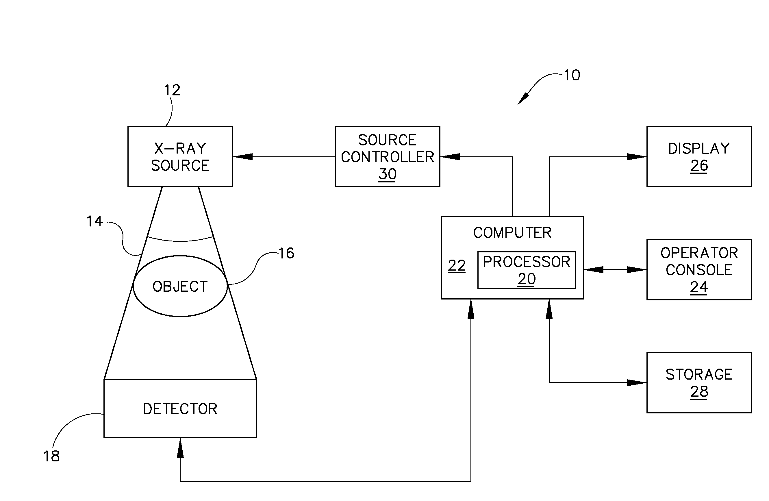
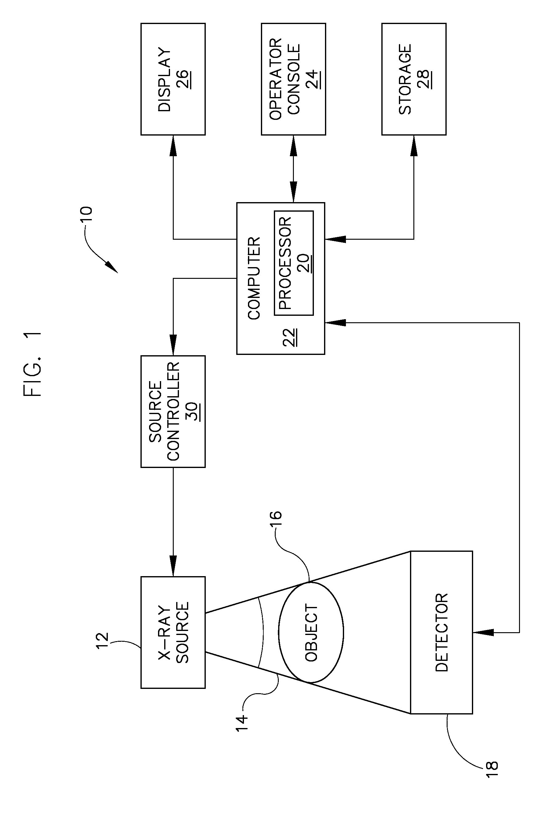
[0023]FIG. 1 is a block diagram of an embodiment of an imaging system 10 designed both to acquire original image data and to process the image data for display and / or analysis in accordance with the invention. It will be appreciated by those skilled in the art that the invention is applicable to numerous medical imaging systems implementing an x-ray tube, such as x-ray or mammography systems. Other imaging systems such as computed tomography (CT) systems and digital radiography (RAD) systems, which acquire image three dimensional data for a volume, also benefit from the invention. The following discussion of x-ray system 10 is merely an example of one such implementation and is not intended to be limiting in terms of modality.

[0024]As shown in FIG. 1, x-ray system 10 includes an x-ray source 12 configured to project a beam of x-rays 14 through an object 16. Object 16 may include a human subject, pieces of baggage, or other objects desired to be scanned. X-ray source 12 may be a conv...


PUM


Abstract

An x-ray tube includes a vacuum chamber, a cathode positioned within the vacuum chamber and configured to emit electrons, and an anode positioned within the vacuum chamber to receive the electrons emitted from the cathode and configured to generate a beam of x-rays from the electrons. The x-ray tube further includes a window positioned to pass the beam of x-rays therethrough, an electron collector structure having an aperture formed therein to allow passage of x-rays therethrough, and a layer attached to the electron collector structure and configured to at least partially absorb or reduce diffraction of x-rays that contact the layer.

Description

BACKGROUND OF THE INVENTION[0001]The invention relates generally to x-ray tubes and, more particularly, to an x-ray tube constructed to address kV-dependent artifacts that result from primary beam interaction with an electron collector of the x-ray tube.[0002]X-ray systems typically include an x-ray tube, a detector, and an assembly to support the x-ray tube and the detector. In some applications, the assembly is rotatable. In operation, an object is located between the x-ray tube and the detector. The x-ray tube typically emits radiation, such as x-rays, toward the object such that the radiation typically passes through the object to impinge on the detector. As radiation passes through the object, internal structures of the object cause spatial variances in the radiation received at the detector. The detector then emits data received, and the system translates the radiation variances into an image, which may be used to evaluate the internal structure of the object. One skilled in t...

Claims


Application Information

Patent Timeline
Patent Type & Authority Applications(United States)
IPC IPC(8): H01J35/18
CPCH01J35/16H01J2235/168H01J2235/1258H01J35/26
Inventor ALLEN, DONALD ROBERTLOUNSBERRY, BRIANVANBOGART, JAMES J.
Owner GENERAL ELECTRIC CO
Why Eureka
Try Eureka