Battery bag

a battery bag and bag body technology, applied in the field of batteries, can solve the problems of battery overload, time-consuming and labor-intensive battery replacement process, and the above-mentioned conventional battery bag assembly suffers from certain drawbacks, so as to prevent battery overload

Inactive Publication Date: 2009-11-12
HARRIS CORP
View PDF4 Cites 48 Cited by
  • Summary
  • Abstract
  • Description
  • Claims
  • Application Information

AI Technical Summary

Benefits of technology

[0014]According to another aspect of the invention, the battery bag assemblies further comprise a clip, an electronic circuit, and/or a securing member. The clip is configured to secure the fabric webbing of the securing means around a periphery of a battery positioned within the battery tray. The electronic circuit can be coupled to the electrical connector sockets. The electronic circuit can be configured to monitor a battery condition and/or prevent battery overload. The electronic circuit can be a printed wiring board secured to the battery tray. The securing

Problems solved by technology

The above described conventional battery bag assembly suffers from certain drawbacks.
This unburying process is time cons

Method used


Image

  • Battery bag
  • Battery bag
  • Battery bag

Examples


Embodiment Construction

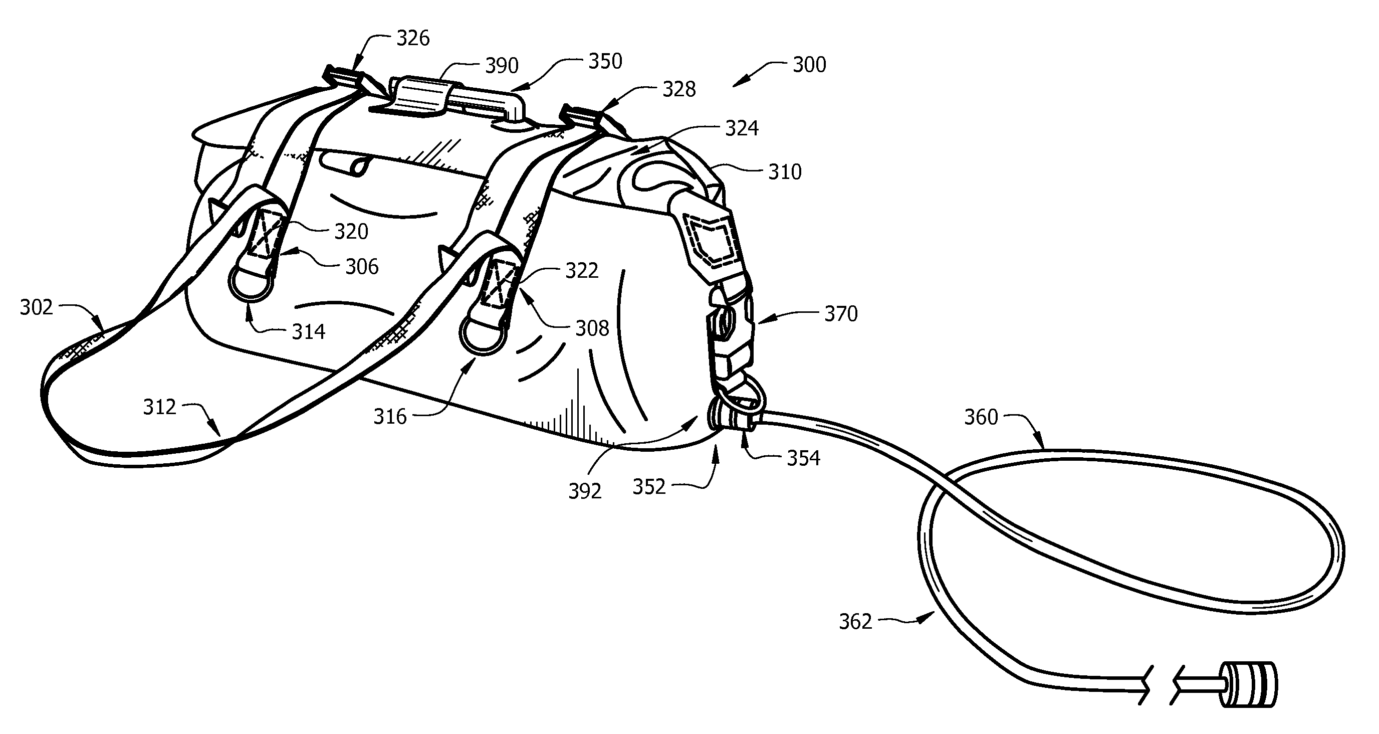
[0028]The invention concerns battery bag assemblies configured for housing batteries. The invention will now be described more fully hereinafter with reference to accompanying drawings, in which illustrative embodiments of the invention are shown. This invention, may however, be embodied in many different forms and should not be construed as limited to the embodiments set forth herein.

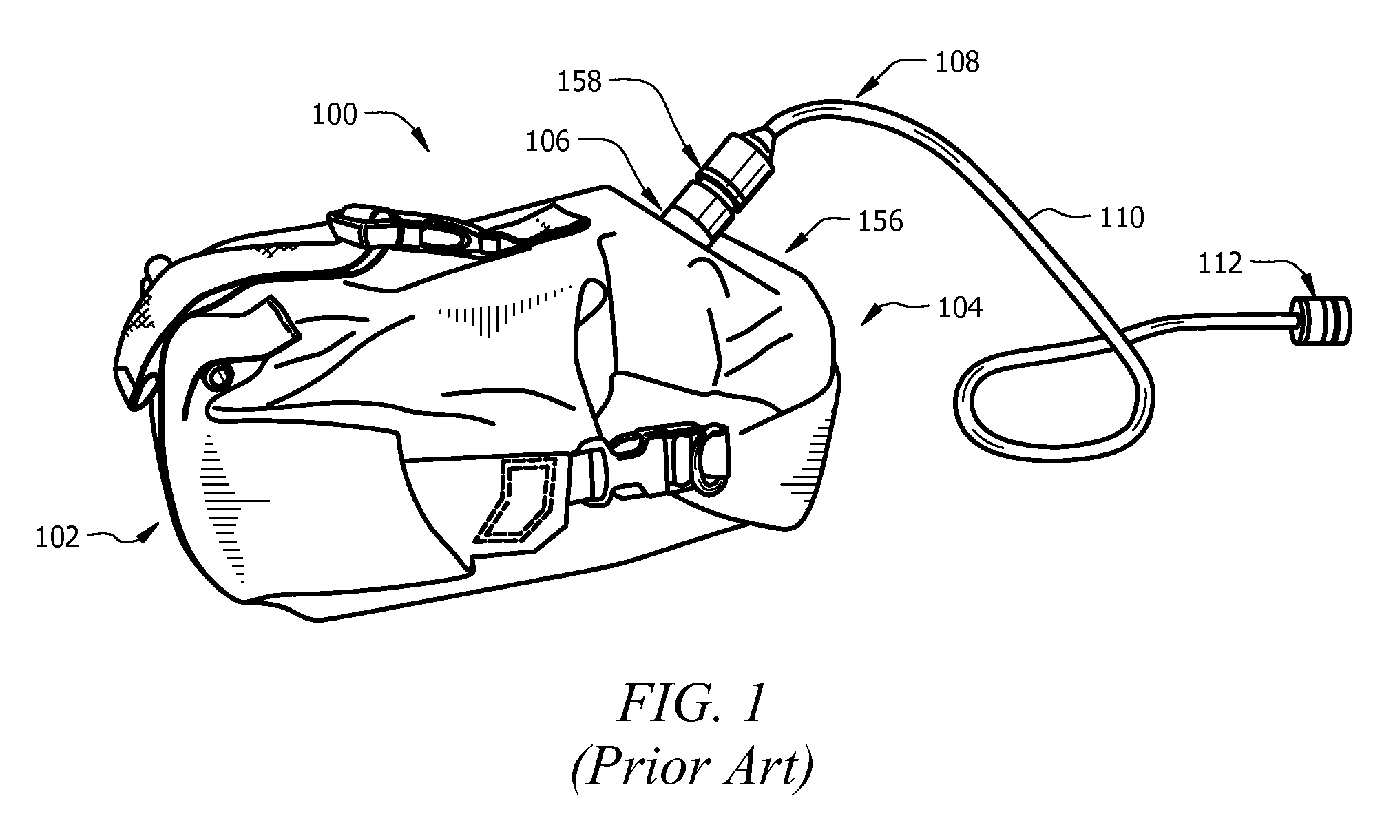
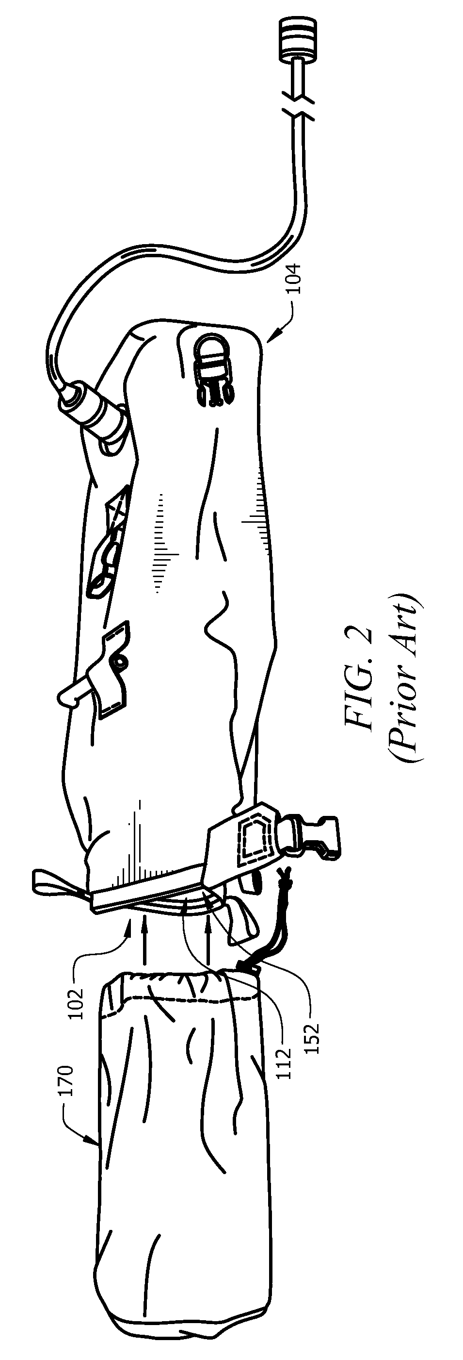
[0029]Before describing the battery bag assemblies of the present invention, it will be helpful in understanding an exemplary environment in which the invention can be utilized. In this regard, it should be understood that the battery bag assemblies of the present invention can be utilized in a variety of different applications where electrical devices are deployed in an unattended and potentially wet environment. Such applications include, but are not limited to, military applications, diving applications, electrical applications, camping applications, hiking applications, and water sport applications...


PUM


Abstract

A battery bag assembly including an elongated watertight bag (WTB), a sealable access port (SAP), a battery tray (BT), a power feed-through (PFT), and an electric power conduit (EPC). SAP (402) has an elongated configuration extending along an elongated length of the WTB. BT (600) is disposed within the WTB so that its elongated configuration is aligned with the elongated length of the WTB. BT has electrical connector sockets (EPSs) mounted thereon for mating with oppositely sexed connectors provided on batteries. PFT (352) is disposed on a wall of the watertight bag. PFT is configured to provide a watertight seal for an electrical conductor passing from an interior of the watertight bag to an exterior of the watertight bag. EPC (360) is electrically connected for coupling electric power from the EPSs on the BT to a remote device.

Description

BACKGROUND OF THE INVENTION[0001]1. Statement of the Technical Field[0002]The invention concerns battery bags, and more particularly, battery bags for use with unattended remote devices deployed in all types of environments.[0003]2. Description of the Related Art[0004]Batteries are commonly used to power certain types of equipment installed in remote locations where no other power source is readily available. For example, batteries can be used to power military communications and surveillance equipment. In order to camouflage such batteries and protect them from the weather, it is known to store the batteries in a protective battery bag. Such battery bags are sometimes buried or partially submerged in water to reduce the likelihood that the batteries will be discovered.[0005]A conventional battery bag is shown in FIGS. 1 and 2. The conventional battery bag 100 is comprised of a water-resistant material so as to protect batteries (not shown) from being exposed to water. The conventio...

Claims


Application Information

Patent Timeline
IPC IPC(8): B65D33/16
CPCA45C13/00
Inventor NOBLES, BARRY
Owner HARRIS CORP
Why Eureka
Try Eureka