Drill body

a drill head and body technology, applied in the field of drill head, can solve the problems of excessive acuteness of the tip part of the drill head, limited positive nose angle of the drill head, and difficulty in cooling and lubricating at least the front portion of the tip part of the cooling liquid, and achieve the effect of moderate cutting for

a drill head and body technology, applied in the field of drill head, can solve the problems of excessive acuteness of the tip part of the drill head, limited positive nose angle of the drill head, and difficulty in cooling and lubricating at least the front portion of the tip part of the cooling liquid, and achieve the effect of moderate cutting for

US20090279965A1Active Publication Date: 2009-11-12SANDVIK INTELLECTUAL PROPERTY AB

Image

  • Drill body
  • Drill body
  • Drill body

Examples


Embodiment Construction

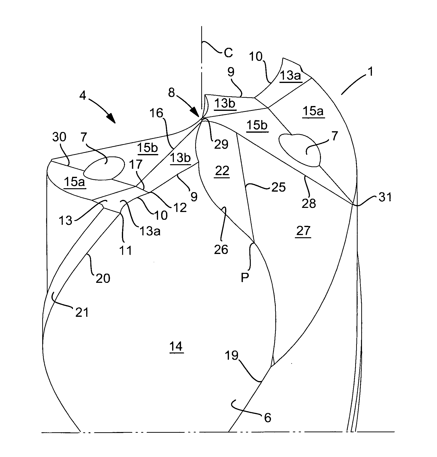
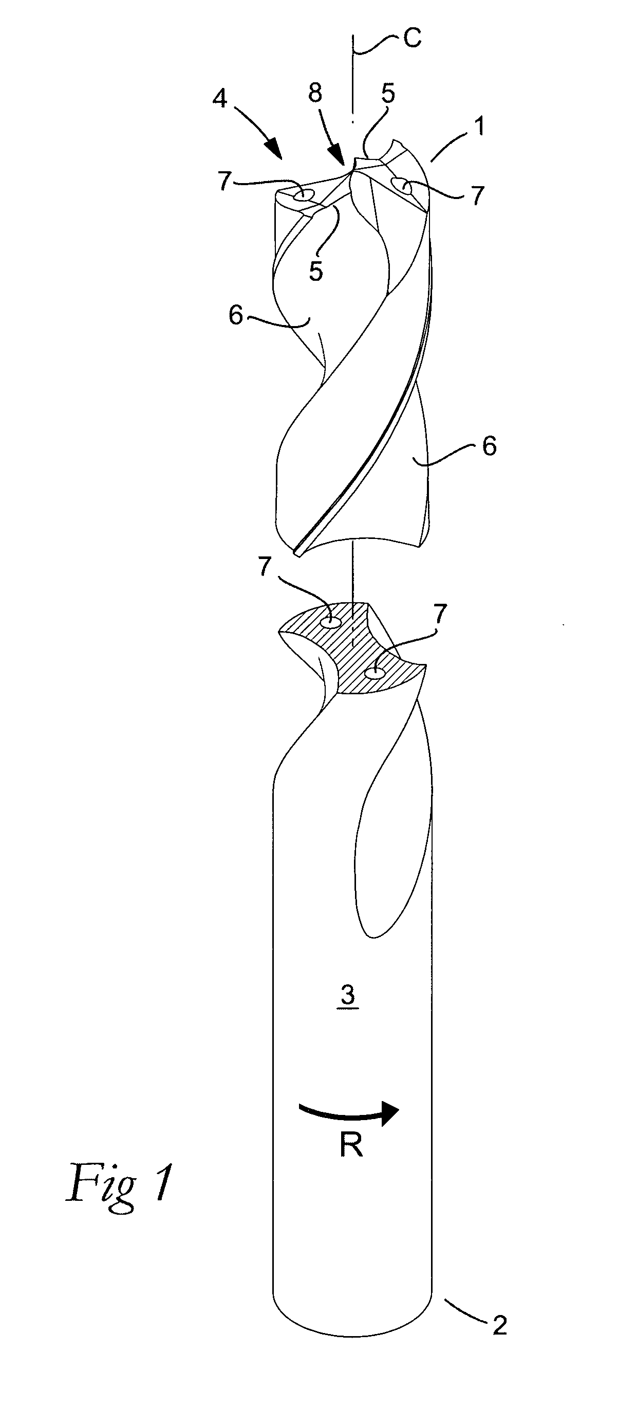
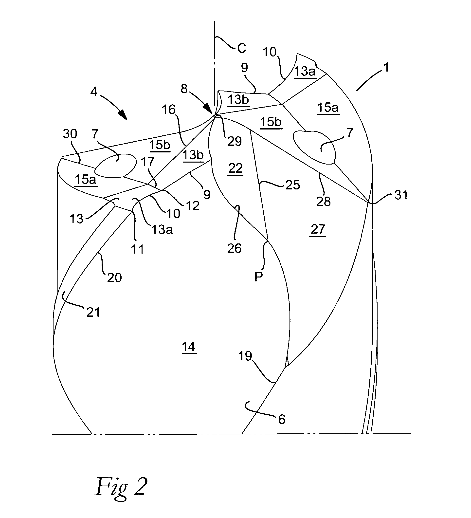
[0019]In an embodiment, the drill body according to the invention is in the form of a twist drill, which henceforth in brief only is denominated “drill”, and which includes front and rear ends 1, 2 between which a center axis C extends around which the drill is rotatable in a predetermined direction of rotation R. A rotationally symmetrical envelope surface 3 is concentric with the center axis C. Along the greater part of the length of the drill, envelope surface 3 is cylindrical, but transforms in front into a slightly conical, forwardly diverging section, which is not perceivable to the naked eye. The diametrical conicity of the front section can be as small as 0.06 / 100 mm. In the front end 1, the drill is formed with a head in its entirety designated 4, which includes two identical cutting edges 5. In front of each cutting edge, as viewed in the direction of rotation, a chip flute 6 is formed, which in this case is spiral or helicoidal having a certain pitch, suitable for the pur...


PUM

PropertyMeasurementUnit
widthaaaaaaaaaa
angleaaaaaaaaaa
angleaaaaaaaaaa

Abstract

A drill body for chip removing machining, including a rotationally symmetrical envelope surface and front and rear ends between which a center axis extends, around which the envelope surface is rotatable in a predetermined direction of rotation. A head is formed in the front end that includes two cutting edges, each one of which includes a first part edge and a second part edge. The first part edge is included in a central tip part having a front end portion situated along the center axis. The second part edge extends between a peripheral end point positioned along the envelope surface and a radially inner end point where the second part edge transforms into the first part edge. The two first part edges converge at a positive nose angle (α) in an axially forward direction, and the two second part edges diverge at a negative angle (β) in the axially forward direction. Each cutting edge is delimited between a chip surface adjacent to a chip flute countersunk in the envelope surface, and a primary clearance surface that transforms into a secondary clearance surface situated rotationally behind the primary clearance surface. Each primary clearance surface includes two part surfaces which mutually form an obtuse angle (χ), and which meet each other in a first chute bottom that runs rotationally rearward from the inner end point of the second part edge. A second chute bottom extends in the extension of the first chute bottom and separates two second part surfaces included in the secondary clearance surface.

Description

[0001]This application claims priority under 35 U.S.C. §119 to Swedish Patent Application No. 0801042-3, filed on May 9, 2008, which is incorporated by reference herein in its entirety.FIELD OF THE INVENTION [0002]The present invention relates generally to a drill body for chip removing machining of the type that includes a rotationally symmetrical envelope surface and front and rear ends between which a center axis extends around which the same is rotatable in a predetermined direction of rotation. A head is formed in the front end and includes two cutting edges, each one of which includes two part edges, a first one of which is included in a central tip part having a front end portion situated along the center axis, and a second one of which extends between a peripheral end point positioned along the envelope surface and a radially inner end point, where the same transforms into the first part edge. The two first part edges converge at a positive nose angle in the direction axiall...

Claims


Application Information

Patent Timeline
12 Nov 2009
Publication
US20090279965A1
IPC
B23B51/06; B23B51/02
CPC
B23B51/02; B23B51/06; B23B2251/04; B23B2251/14; Y10T408/9093; Y10T408/9065; Y10T408/9097; Y10T408/899
Inventors
SOITTU, KARI