Electronic control system for vehicles
a technology of electronic control system and vehicle, which is applied in the direction of testing/monitoring control system, process and machine control, etc., can solve the problems of erroneously indicating abnormality in the vehicle maintenance shop, unable to read out abnormality data indicating abnormality detected, and the standby ram will lose its storage contents
- Summary
- Abstract
- Description
- Claims
- Application Information
AI Technical Summary
Problems solved by technology
Method used
Image

Examples
first embodiment
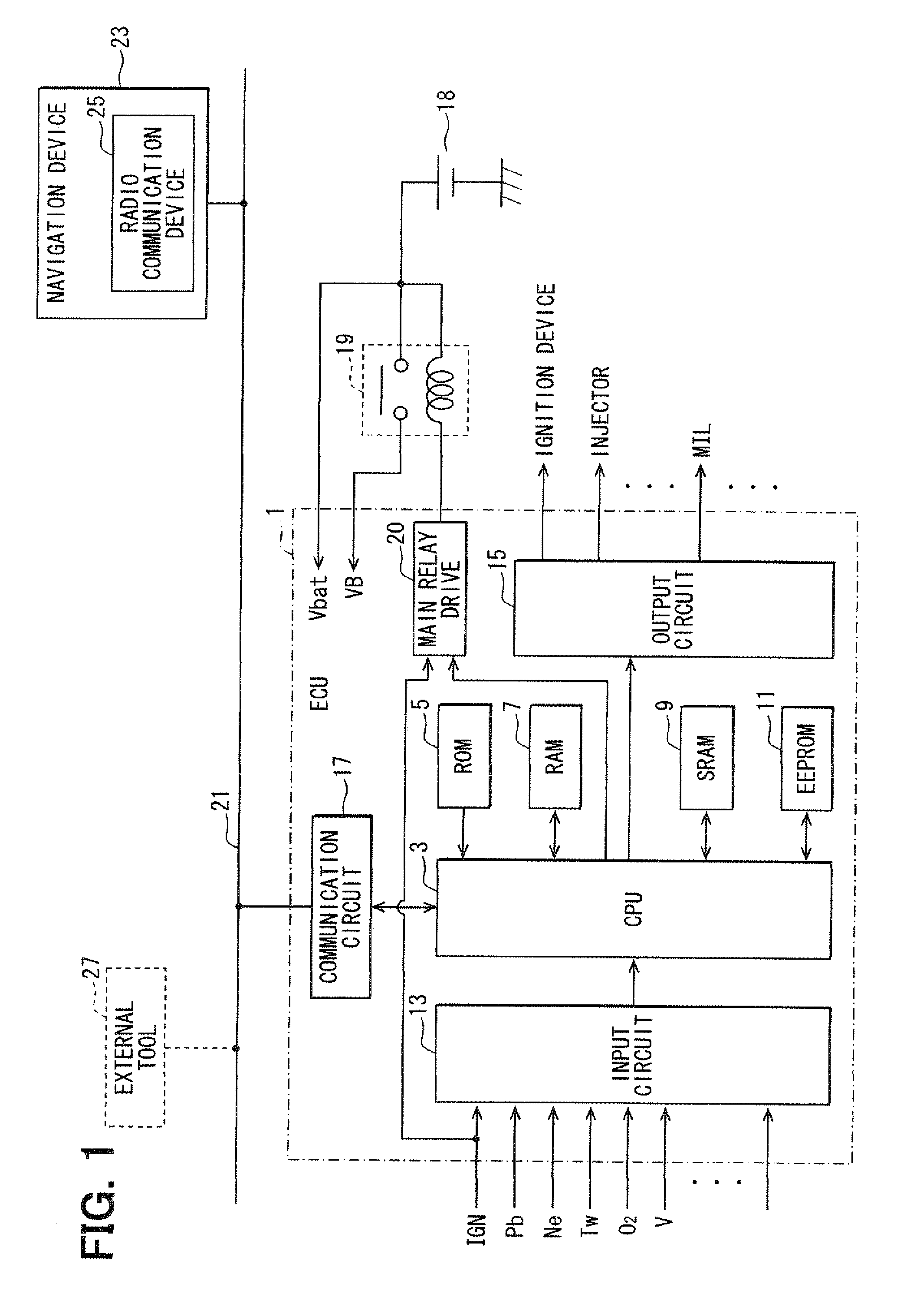
[0047]Referring first to FIG. 1, an electronic control system in accordance with the first embodiment has an electronic control unit (ECU) 1 assembled to a vehicle 35 (FIG. 5) to control a vehicle engine (not shown) and perform diagnosis.
[0048]The ECU 1 includes a central processing unit (CPU) 3, a read only memory (ROM) 5 that stores programs executed by the CPU 3 and data referred to at the time of program execution, a random access memory (RAM) 7 for temporarily storing data, a standby RAM (SRAM) 9 to which electric power corresponding to a voltage Vbat is continuously supplied as a back-up power for backing up data storage even in the event normal electric power is lost, an electrically erasable programmable read only memory (EEPROM) 11 that is one of rewritable nonvolatile memories, an input circuit 13, and an output circuit 15.
[0049]Various signals are input into the CPU 3 through the input circuit 13, the signals providing input data for controlling the engine. The various si...
second embodiment
[0115]In the second embodiment shown in FIGS. 10 and 11, the condition for switching the condition flag from the off-state to the on-state, that is, condition for switching the memory area of storing the DTC in the EEPROM 11, is differentiated from that in the first embodiment.
[0116]In the second embodiment shown in FIG. 10, a managing device 43 including a computer is provided in a manufacturing plant 41 of the vehicle 35 into which the ECU 1 and the navigation device 23 are assembled. Management data indicating whether the manufacturing of each vehicle 35 has been completed is input to the managing device 43. The managing device 43 regularly transmits the management data to the data processing device 33 through the public line or the dedicated line according to a given time period or every time the management data is updated. The management data includes, for example, data indicative of the vehicle identification number and whether the vehicle associated with the vehicle identific...
third embodiment
(Modification of Third Embodiment)
[0131]The third embodiment may be modified such that the navigation device 23 of the vehicle 35 executes the similar processing as that of FIG. 13.
[0132]Specifically, since the navigation device 23 of the vehicle 35 continuously detects the position of the vehicle 35, it may check whether the vehicle 35 has moved out of the specified area 45. If it is determined that the vehicle 35 has moved out of the specified area, the area leaving data is transferred to the ECU 1 through the communication line 21.
PUM
 Abstract
Description
Claims
Application Information
 - R&D Engineer
- R&D Manager
- IP Professional
- Industry Leading Data Capabilities
- Powerful AI technology
- Patent DNA Extraction
Browse by: Latest US Patents, China's latest patents, Technical Efficacy Thesaurus, Application Domain, Technology Topic.
© 2024 PatSnap. All rights reserved.Legal|Privacy policy|Modern Slavery Act Transparency Statement|Sitemap