Disc brake device

a disc brake and disc technology, applied in the direction of brake types, slack adjusters, braking elements, etc., can solve problems such as the phenomenon of brake noise, and achieve the effect of reliably suppressing the brake noise phenomenon

Inactive Publication Date: 2009-11-19
TOYOTA JIDOSHA KK
View PDF5 Cites 11 Cited by
  • Summary
  • Abstract
  • Description
  • Claims
  • Application Information

AI Technical Summary

Benefits of technology

[0006]Meanwhile, when the rotational moment acting on the brake pad varies dependent on the surface pressure distribution between the rotor surface of the disc rotor and the pad member of the brake pad at the time of forward braking, for example, the contact state (contact angle) between the protruded forward braking torque transmitting part in the backing metal of the brake pad and the recessed forward braking torque receiving part in the mounting may fluctuate unstably, thereby making it easier for the backing metal of the brake pad to vibrate, thus causing a so-called brake noise phenomenon.
[0007]It is therefore an object of the present invention to provide a disc brake apparatus which can reliably suppress the brake noise phenomenon by keeping a stable contact state between a torque transmitting part of a brake pad and a torque receiving part of a mounting.
[0009]At the time of braking where the main body member of the brake pad is pressed against the disc rotor in the disc brake apparatus in accordance with the present invention, the brake torque fed to the main body member of the brake pad from the disc rotor is received by the torque receiving part of the mounting by being transmitted thereto through the torque transmitting member of the brake pad. Here, the rotational moment acting on the brake pad from the disc rotor is absorbed by the main body member of the brake pad rotating relative to the torque transmitting member, so as to be restrained from being transmitted to the torque transmitting member. As a result, the contact state between the torque transmitting member of the brake pad and the torque receiving part of the mounting is held stable, so as to restrain the brake pad from vibrating, thereby reliably suppressing the brake noise phenomenon.
[0013]In the disc brake apparatus in accordance with the present invention, the rotational moment acting on the brake pad at the time of braking is absorbed by the main body member of the braking pad rotating relative to the torque transmitting member, so as to be restrained from being transmitted to the torque transmitting member. Therefore, the present invention can keep a stable contact state between the torque transmitting member of the brake pad and the torque receiving part of the mounting, thereby restraining the brake pad from vibrating, thus reliably suppressing the brake noise phenomenon.

Problems solved by technology

Meanwhile, when the rotational moment acting on the brake pad varies dependent on the surface pressure distribution between the rotor surface of the disc rotor and the pad member of the brake pad at the time of forward braking, for example, the contact state (contact angle) between the protruded forward braking torque transmitting part in the backing metal of the brake pad and the recessed forward braking torque receiving part in the mounting may fluctuate unstably, thereby making it easier for the backing metal of the brake pad to vibrate, thus causing a so-called brake noise phenomenon.

Method used


Image

  • Disc brake device
  • Disc brake device
  • Disc brake device

Examples


Embodiment Construction

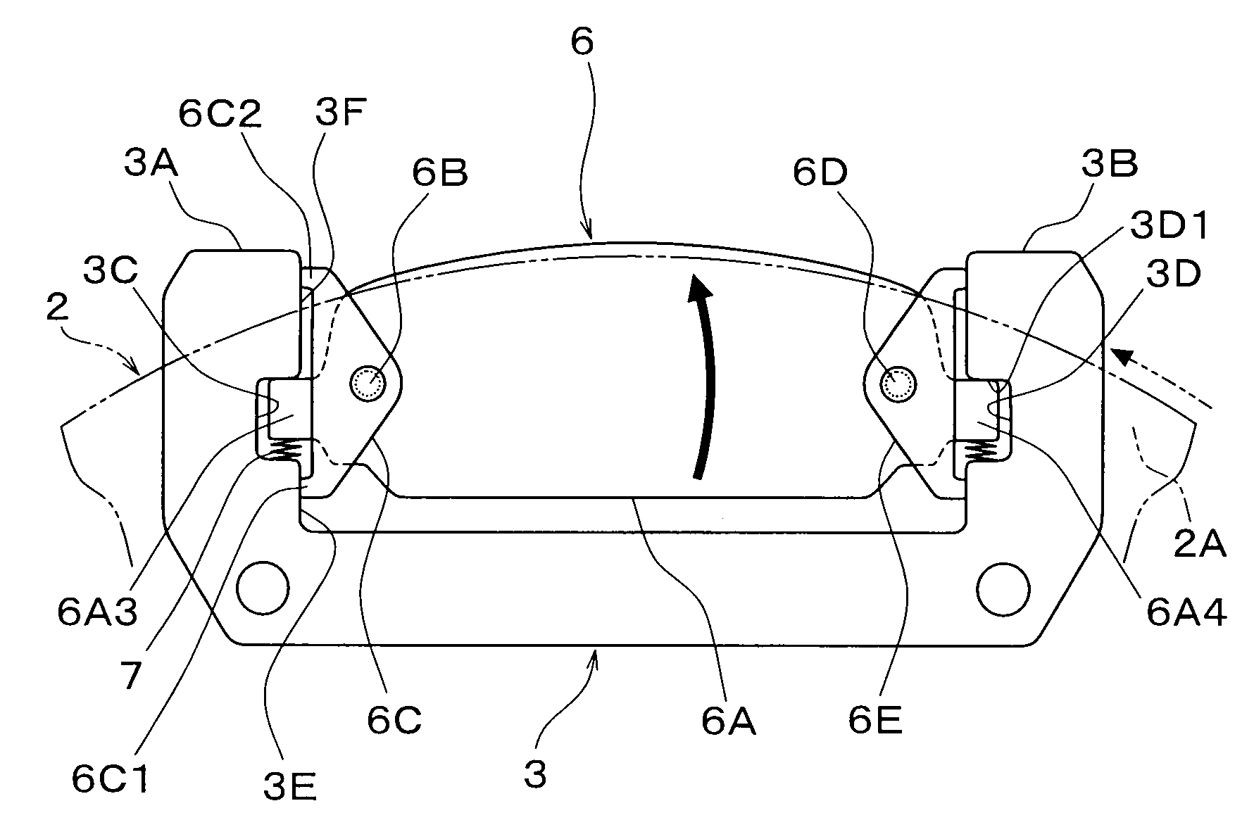
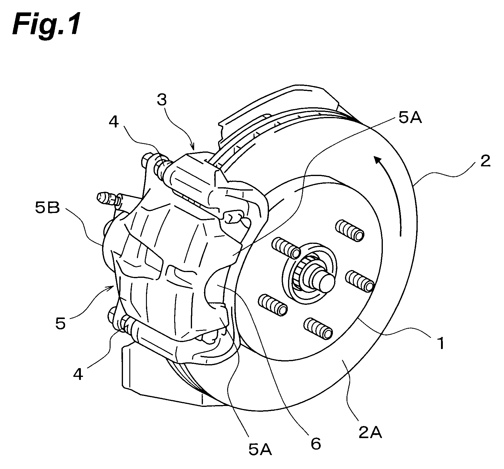
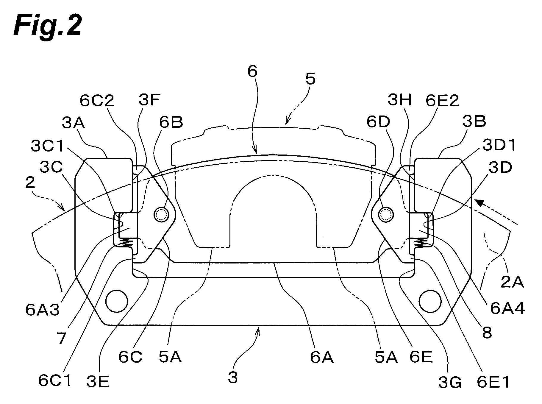
[0019]In the following, the best embodiments of the disc brake apparatus in accordance with the present invention will be explained with reference to the drawings. In the drawings for reference, FIG. 1 is a perspective view showing the exterior of the disc brake apparatus in accordance with an embodiment of the present invention, FIG. 2 is a front view of a brake pad mounted to the disc brake apparatus shown in FIG. 1, and FIG. 3 is a plan view of the brake pad shown in FIG. 2.

[0020]The disc brake apparatus in accordance with this embodiment is constructed for a vehicle and comprises a disc rotor 2 which is secured to a hub 1 of an axle and rotates integrally therewith, a mounting (torque member) 3 supported by an undepicted suspension part or the like of a vehicle body and arranged so as to straddle an outer peripheral part of the disc rotor 2, a floating caliper 5 which is attached to the mounting 3 with a pair of slide pins 4, 4 such as to be slidable in parallel with the rotary ...


PUM


Abstract

A disc brake apparatus that can keep a stable contact state between a torque transmitting part of a brake pad and a torque receiving part of a mounting, so as to reliably suppress a brake noise phenomenon. At the time of forward braking where a main body member of a brake pad is pressed against a disc rotor, the rotational moment acting on the main body member of the brake pad from the disc rotor is absorbed by the main body member rotating relative to a forward braking torque transmitting member about one pin joint, so as to be restrained from being transmitted to the forward braking torque transmitting member. As a result, the respective contact states between two torque transmitting protrusions formed in the forward braking torque transmitting member of the brake pad and torque receiving surfaces formed in a forward braking torque receiving part of a mounting are held stable.

Description

TECHNICAL FIELD[0001]The present invention relates to a disc brake apparatus which is mounted as a braking apparatus to a vehicle, for example.BACKGROUND ART[0002]A disc brake apparatus has conventionally been known in general, which is constructed such that rotor surfaces of a disc rotor are held between a pair of brake pads, while a brake torque fed to the brake pads from the disc rotor is received by a torque receiving part of a mounting (torque member) on the vehicle body side, so as to yield a braking force.[0003]In general, the brake pads in such a disc brake apparatus have a structure in which pad members coming into frictional contact with the rotor surfaces of the disc rotor under pressure are joined to backing metals. One end part of the backing metal to become the turning-out side of the disc rotor when the vehicle runs forward is integrally formed with a protruded forward braking torque transmitting part, while the other end part of the disc rotor to become the turning-o...

Claims


Application Information

Patent Timeline
Patent Type & Authority Applications(United States)
IPC IPC(8): F16D65/097
CPCF16D65/092F16D65/095F16D65/0976F16D65/0973F16D65/0974F16D65/0972
Inventor MATSUSHIMA, TORU
Owner TOYOTA JIDOSHA KK
Why Eureka
Try Eureka