Electrical stimulation and infusion introducer assembly

a technology of electric stimulation and introducer needle, which is applied in the field of electrical stimulation and infusion introducer assembly, can solve the problems of pushing the introducer needle, significant pain to the patient, and tissue heating,

a technology of electric stimulation and introducer needle, which is applied in the field of electrical stimulation and infusion introducer assembly, can solve the problems of pushing the introducer needle, significant pain to the patient, and tissue heating,

US20090287140A1Inactive Publication Date: 2009-11-19NEUROTHERM

Image

  • Electrical stimulation and infusion introducer assembly
  • Electrical stimulation and infusion introducer assembly
  • Electrical stimulation and infusion introducer assembly

Examples


Embodiment Construction

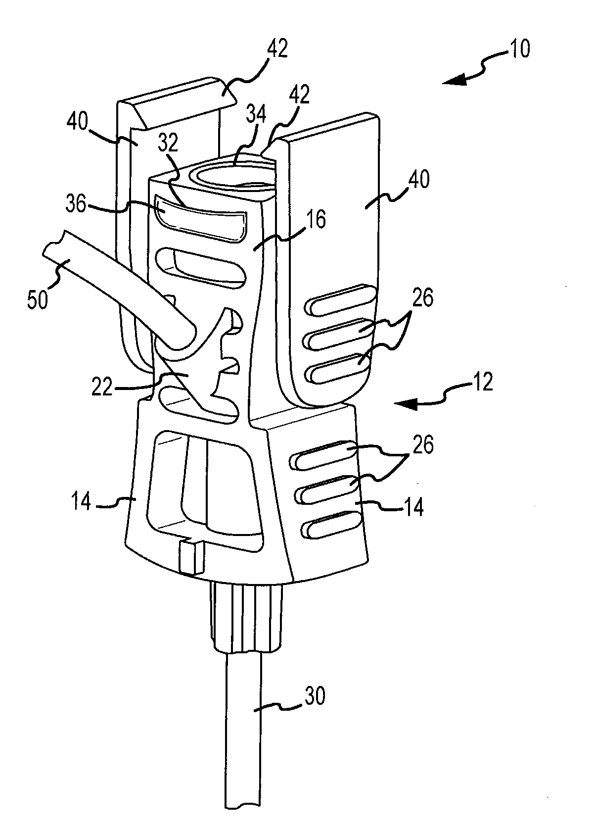
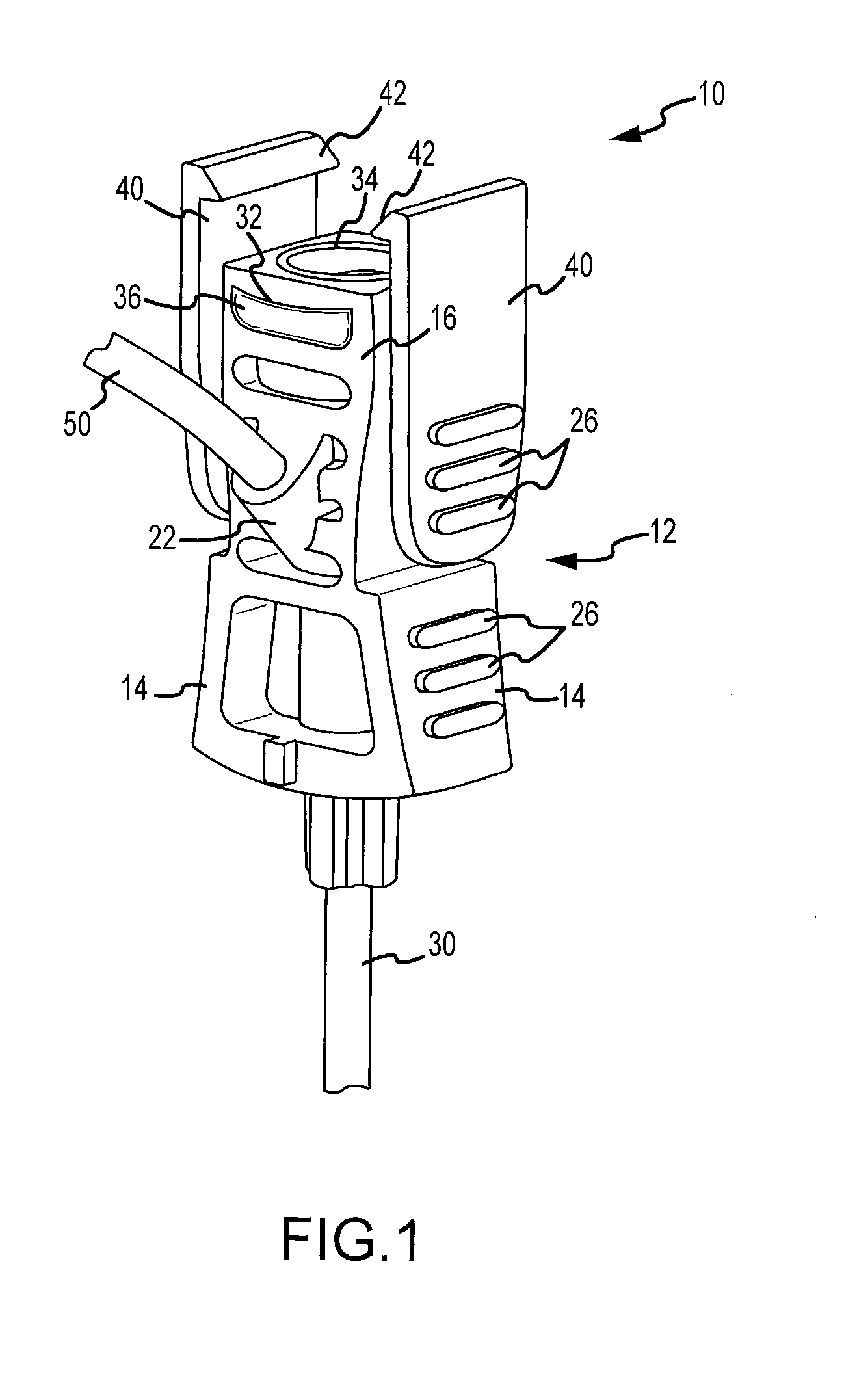
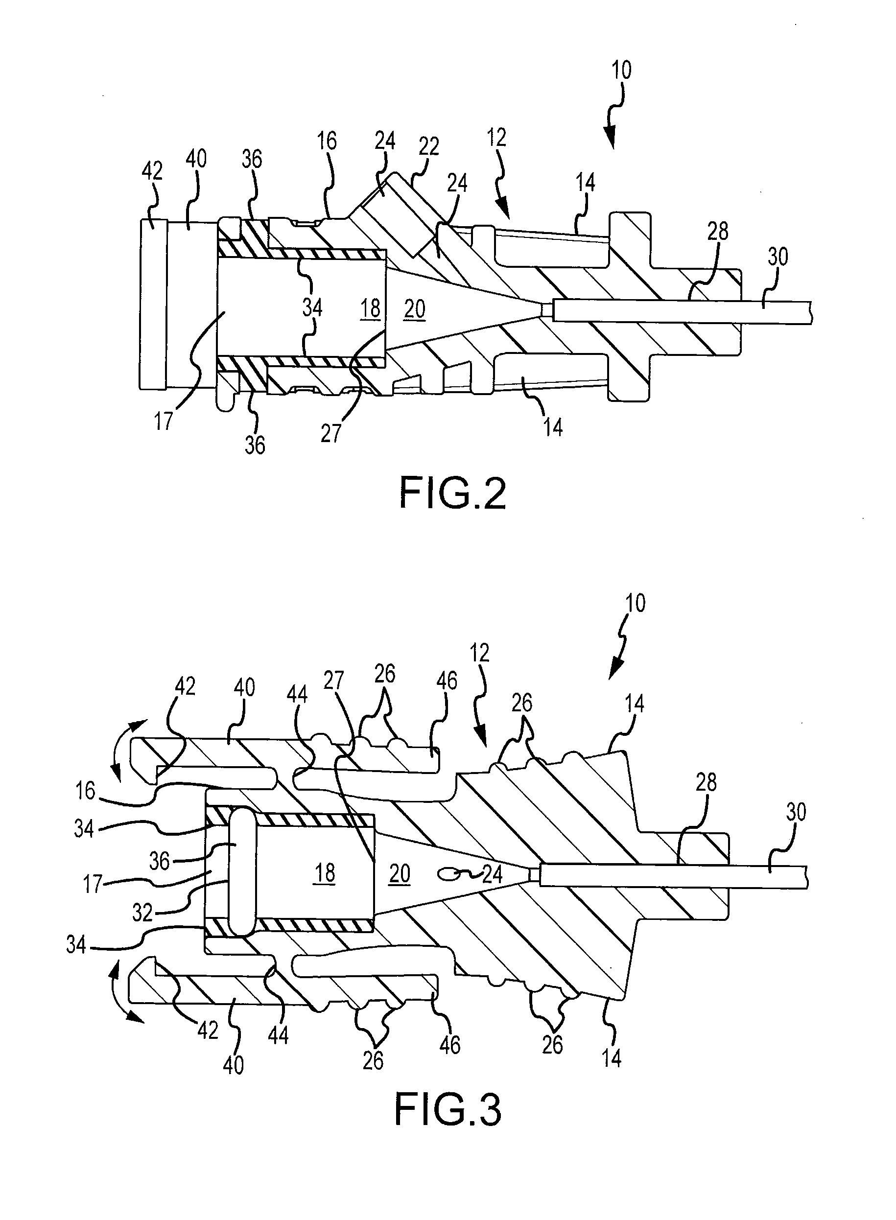
[0021]Referring to FIGS. 1-4, the electrical stimulation and infusion introducer assembly 10 is shown. The introducer assembly 10 includes a hub or body 12. The hub / body 12 may be further defined as having a needle receiving portion 14 and an extension 16 that receives an electrode. Portion 14 includes a needle port 28 that receives an introducer needle 30. The body 12 further includes a central passageway 18 that extends between the open end 17 and the needle port 28. The central passageway includes a substantially cylindrical portion communicating with the open end 17, and a narrowing portion 20 that communicates with the needle port 28. A side port 22 is formed on the hub extension 16. The side port 22 includes a side port passageway 24 that communicates with the narrowing portion of the central passageway 18. As shown in FIG. 2, the side port passageway 24 includes an upper cylindrical portion that may be sized to frictionally engage a length of tubing 50. A gasket 34 is receive...


PUM


Abstract

An electrical stimulation and infusion introducer assembly is provided for connection to an electrical electrode / electrode. The electrode extends through the lumen of an introducer needle of the introducer assembly. The introducer assembly includes a side port for introduction of liquids through the introducer needle without having to remove the electrode. The side port communicates with the central passageway of the introducer assembly, and the central passageway in turn communicates with the lumen of the needle.

Description

FIELD OF THE INVENTION[0001]The present invention relates generally to processes, systems, and devices for the treatment of pain, neurological disorders, and related to neural dysfunction. More specifically, the present invention relates to a device to produce therapeutic lesions or tissue alterations by a stimulation probe having an electrode element that delivers high-frequency energy to targeted tissue, and further more specifically to an electrical stimulation and infusion introducer assembly that can deliver an anesthetic to the targeted issue while holding the electrode element during a procedure without having to remove the stimulation probe from the introducer assembly.BACKGROUND OF THE INVENTION[0002]It is well known to use radio-frequency generators and electrodes to apply radio-frequency energy in order to treat pain and / or to modify neural tissue for other treatment purposes. Heating of the tissue is caused by RF resistance power dissipation. The amount of heat applied i...

Claims


Application Information

Patent Timeline
19 Nov 2009
Publication
US20090287140A1
IPC
A61M5/158; A61B18/14
CPC
A61B18/14; A61B19/201; A61M39/02; A61M39/06; A61N1/403; A61M2205/054; A61N1/36017; A61N1/36021
Inventors
RITTMAN, III, WILLIAM J.